

Hardware components | ||||||
 |
| × | 1 | |||
 |
| × | 1 | |||
Software apps and online services | ||||||
 |
| |||||
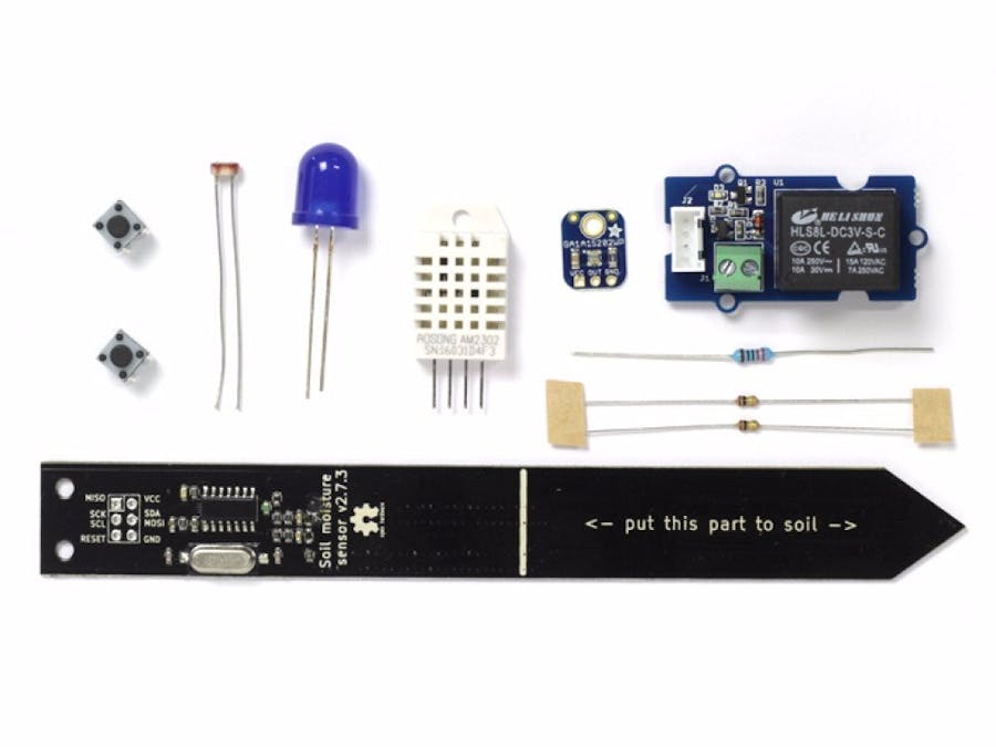
The Rural Hack Kit is the perfect electronic set to get you started hacking your farm, garden, or plants on your balcony.
The kit includes the essentials for monitoring the environment of our green silent friends: an accurate soil moisture sensor, a precise digital light sensor module, and a temperature and humidity sensor.
Moreover, to automate your greenhouse, the kit features a relay module that you can use to control a water valve, a fan, or a lamp.
KIT CONTENTS
- Humidity Sensor (DHT22)
- Log-scale Analog Light Sensor (Ga1a12s202 in its Adafruit's Flavour)
- Soil Moisture Sensor (aka the slim chirp) from Miceuz
- Grove Relay Module from Seeed
- Resistors / pushbuttons / connectors
This is the first of a series of tutorial that will teach how to use the modules in the kit. In this tutorial we are going to learn how to connect the sensors and actuators to the Arduino, read their data, and interact with them.
In the next tutorials you will learn how to connect the sensor to cloud services and take care of your garden remotely.
DHT22 humidity and temperature sensorSensor Specs
The DHT22 is a digital sensor capable of reading environmental temperature and humidity.
- Low cost
- 3 to 5V power and I/O
- 2.5mA max current use during conversion (while requesting data)
- Good for 0-100% humidity readings with 2-5% accuracy
- Good for -40 to 80°C temperature readings ±0.5°C accuracy
- No more than 0.5 Hz sampling rate (once every 2 seconds)
- Body size 27mm x 59mm x 13.5mm (1.05" x 2.32" x 0.53")
- 4 pins, 0.1" spacing
- Weight (just the DHT22): 2.4g
Connections
Connecting to to the sensor is very easy. As shown in the picture connect
- the first pin to VCC on your board.
- The second pin is the data Out pin, connect that to any digital pin on the board.
- leave the third pin disconnected.
- connect the forth pin to ground.
Setup & test
Before you can try the sensor you need to install its library. Search for dht on the library manager and install the library.
Now you can just upload the test sketch that will get the data from the sensor and print them to the serial port.
#include <SimpleDHT.h>
// for DHT22,
// VCC: 5V or 3V
// GND: GND
// DATA: 6
int pinDHT22 = 6;
SimpleDHT22 dht22;
void setup() {
 Serial.begin(115200);
}
void loop() {
 // start working...
 Serial.println("=================================");
 Serial.println("Sample DHT22...");
 // read without samples.
 // @remark We use read2 to get a float data, such as 10.1*C
 //    if user doesn't care about the accurate data, use read to get a byte data, such as 10*C.
 float temperature = 0;
 float humidity = 0;
 int err = SimpleDHTErrSuccess;
 if ((err = dht22.read2(pinDHT22, &temperature, &humidity, NULL)) != SimpleDHTErrSuccess) {
   Serial.print("Read DHT22 failed, err="); Serial.println(err);delay(2000);
   return;
 }
 Serial.print("Sample OK: ");
 Serial.print((float)temperature); Serial.print(" *C, ");
 Serial.print((float)humidity); Serial.println(" RH%");
 // DHT22 sampling rate is 0.5HZ.
 delay(2500);
}
You can now open the serial monitor and you should be able to see the temperature and humidity value printed there.
I2C Soil moisture sensorThe soil moisture sensor provided with the kit is probably one of the most reliable and at the same time cheap sensor for DIY soil moisture measurement on the market.
Classic soil moisture sensor, (the one that look like a fork with two electrodes) measure resistance between the two electrodes planted in the soil; High resistance between the electrodes means that the soil is not conducting electricity therefore it is probably dry; low resistance means that the electricity is flowing easily between the two electrodes, that's what happens when the sensor is in water or in a wet soil.
The downside of the described techniques is that the copper on the electrodes quickly get rusty, hence after a while, the reading from those sensor become not accurate anymore.
The sensor provided in the kit, uses capacitive sensing to measure the capacitance of the medium it's surrounded by: Wet soil for instance has a higher capacitance than dry soil or air. Instead of electrodes it features a capacitive antenna that doesn't need to stay in direct contact with the soil, this protects the sensor making it's reading reliable and accurate in time.
The sensor can be read via I2C protocol and provides these features:
- Soil moisture sensing
- Light sensing
- Temperature sensing
- Reset chip
- I2C address change
- Deep sleep
Sensor Specs
- Version 2.7.5
- Supply voltage 3.3V - 5V
- Current consumption: 1.1mA @ 5V, 0.7mA @ 3.3V when idle, 14mA @ 5V, 7.8mA @ 3.3V when taking a measurement. When constantly polling sensor at full speed, current consumption averages to 4.5mA @ 5V, 2.8mA @ 3.3V
- Operating temperature 0°C - 85°C
- Moisture reading drift with temperature - <10% over full temp range
- Don't forget to provide pullups for SCL and SDA lines
- Default I2C address is 0x20 (hex)
Connections
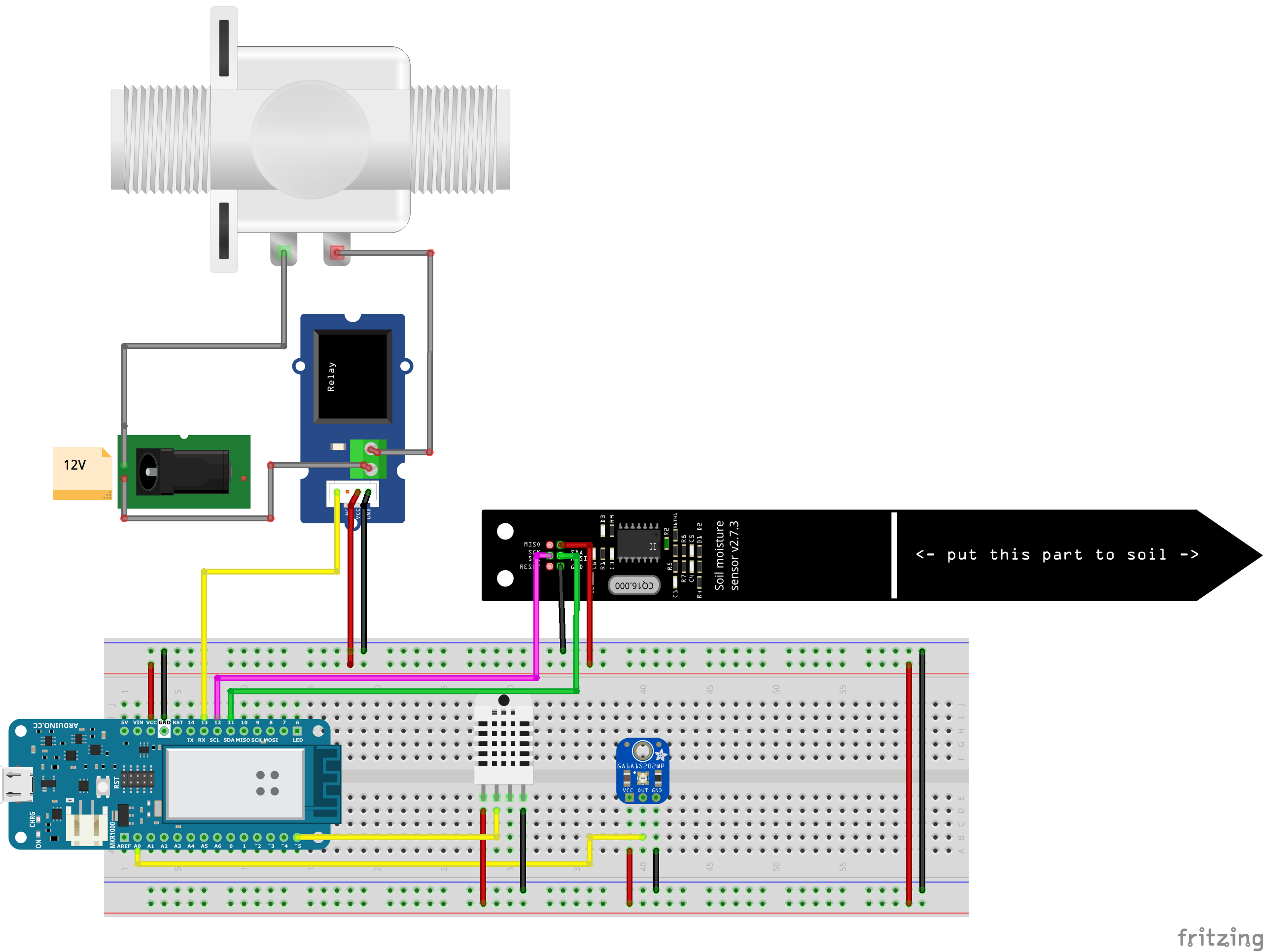
The connection to the sensor is done via i2c, depending on the board you are using you might have different pin assigned to I2C;
If you are workng with a MKR1000 connect:
- VCC to VCC
- GND to GND
- SCL to 12
- SDA to 11
Setup & test
First of all install the I2CSoilMoistureSensor Library: open the library manager, search for I2CSoilMoistureSensor and install the library.
Upload now the example sketch and you should be able to see the measured data.
#include <I2CSoilMoistureSensor.h>
#include <Wire.h>
I2CSoilMoistureSensor sensor(0x60);
void setup() {
 Wire.begin();
 Serial.begin(9600);
 sensor.begin(); // reset sensor
 delay(1000); // give some time to boot up
 Serial.print("I2C Soil Moisture Sensor Address: ");
 Serial.println(sensor.getAddress(),HEX);
 Serial.print("Sensor Firmware version: ");
 Serial.println(sensor.getVersion(),HEX);
 Serial.println();
}
void loop() {
 while (sensor.isBusy()) delay(50); // available since FW 2.3
 Serial.print("Soil Moisture Capacitance: ");
 Serial.print(sensor.getCapacitance()); //read capacitance register
 Serial.print(", Temperature: ");
 Serial.print(sensor.getTemperature()/(float)10); //temperature register
 Serial.print(", Light: ");
 Serial.println(sensor.getLight(true)); //request light measurement, wait and read light register
 sensor.sleep(); // available since FW 2.3
}
This very cheap sensor module produced by Adafruit it’s considerably more accurate that a old fashion photo-resistor you might have used in other project.
Most light sensors have a linear relationship with light levels, which means that they're not very sensitive to changes in darkened areas and 'max' out very easily when there's a lot of light.
This sensor is logarithmic over a large dynamic range of 3 to 55,000 Lux, so it has a lot of sensitivity at low light levels but is also nearly impossible to "max out" so you can use it indoors or outdoors without changing code or calibration.
Sensor Specs
- Power with 2.3-6V
- Onboard 68K load resistor for max 3V analog output
- 0.2 grams
- 0.4” x 0.5" x 0.06" (10mm x 13mm x 1.5mm)
- 0.1” (2.5mm) mounting hole
You can get the full datasheet here
Connections
Reading the light intensity with this sensor is is as easy as reading a analog from an analog sensor.
Just connect the power via the VCC and GND, and connect the OUT pin to a analog input on your board.
- VCC to 3.3V or 5V depending on your board voltage
- OUT to AO on your board
- GND to GND on your board
Setup & test
You won’t need any library to use it just read the value from the A0 pin using analogueRead() function.
Max output value of this sensor is 3.3V, If you are using a 3.3V board like the mkr1000 you should have accurate readings out of the box.
!!! If your board works at 5v, have a look at this adafruit tutorial, you will find a handy trick on how to use a external analogue reference value.
A simple conversion from analogue readings to lux is done in the provided example sketch below.
Upload it to your board and you should be able accurately measure the light in the room.
/*
 Test sketch for the Adafruit Analog Light Sensor
 by Bill Earl
 for Adafruit Industries
 Connect sensor output to Analog Pin 0
 Connect VCC to VCC and GND to GND
*/
int sensorPin = A0;    // select the input pin for the potentiometer
float rawRange = 1024; // 3.3v
float logRange = 5.0; // 3.3v = 10^5 lux
void setup()
{
 analogReference(EXTERNAL); //
 Serial.begin(9600);
 Serial.println("Adafruit Analog Light Sensor Test");
}
void loop()
{
 // read the raw value from the sensor:
 int rawValue = analogRead(sensorPin);
 Serial.print("Raw = ");
 Serial.print(rawValue);
 Serial.print(" - Lux = ");
 Serial.println(RawToLux(rawValue));
 delay(1000);
}
float RawToLux(int raw)
{
 float logLux = raw * logRange / rawRange;
 return pow(10, logLux);
}
The last important piece of the kit is the relay. The relay is an electromechanical component that you can use to control big loads from your Arduino. You can attach water pumps, fans and basically anything that can be switched on or off.
!!! watch out !!! connecting big loads like 220V lamps is dangerous!!! Adopt all the required precautions if you are working with more than 120V.
the relay provided in the kit can be controlled also by a 3.3v devices, it is therefore very easy to connect it to a MKR1000.
Connections
Connecting the relay to the Arduino is very simple, just connect the 3 wires that come with it to the Arduino.
- VCC to VCC
- GND to GND
- SIG to pin9 on the Arduino.
The two screw terminal on the module are where you should attach your load: a fan a pump, a light-strip or anything else.
Setup & test
To test that everything is working correctly we are just going to upload a blink sketch on our board.
Every time the led switch on or off you should hear a mechanical noise inside the relay housing.
int RELAY_PIN=9;
void setup() {
 pinMode(LED_BUILTIN, OUTPUT);
 // initialize digital pin RELAY_BUILTIN as an output.
 pinMode(RELAY_PIN, OUTPUT);
}
void loop() {
 digitalWrite(LED_BUILTIN, HIGH);
 pinMode(RELAY_PIN, HIGH);          // open the circuit
 delay(1000);
 digitalWrite(LED_BUILTIN, LOW);   // close the circuit
 pinMode(RELAY_PIN, LOW);
 delay(1000);                       // wait for a second
}


Comments