In today's world, bee populations are in decline and the livelihood of beekeepers is at risk. To address this problem, our team at Polytech has developed an innovative solution to monitor the health and well-being of bee hives.
Here is a link to a small presentation video :
Presentation poster
Our system uses basic sensors and wireless technology to collect data on the weight, temperature, humidity, and buzzing frequencies of the hive, providing beekeepers with valuable insights into the hive's activity and overall health.
Our goal is to help protect bees and support the livelihoods of beekeepers by making it easier to manage and maintain healthy hives.
Report of the project progress:
- Initially, we began by researching and selecting the appropriate sensors for data retrieval on the bee hive, including weight, temperature, luminosity, humidity, and hive buzzing frequencies, with the help of a microphone and an amplifier;
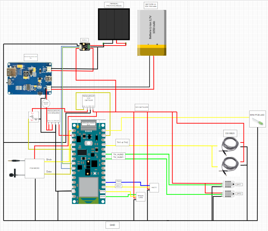
refer to the diagram given for the different connections and the pins that we used. It is coded and colored
- Then we worked on The Thing Network to know how to connect the LoRa module with TTN and share this data to a website (ubidots, beep monitor)
You can follow this tutoriel that is well explained https://www.thethingsnetwork.org/docs/devices/uno/quick-start/
- Then we moved on to designing and creating our PCB (printed circuit board) for housing these sensors and ensuring proper connections between them.
- We also did a PCB for the Audio part, it include an MAX4468 Micropower
Our PCB included the MAX4468 Micropower amplifier to minimize noise and parasitic residues.
Here you can see our PCB with the Max4468 micropower
The initial circuit
Our PCB
- Once the PCB was completed, we proceeded to testing each sensor individually to ensure their accuracy and proper functioning. We used the example code gived by their libraries
- Next, we integrated the sensors with our microcontroller, and wrote code to properly collect and transmit the data collected.
We also analyzed the consumption of the latter using an Otii module, here is a quick tutorial : https://www.youtube.com/watch?v=bMf4I1TQzco
- Simultaneously, we also worked on developing the enclosure for our system, using a waterproof PVC casing, that we drilled holes to run our sensor wires through.
- We then continued to test and refine the system as a whole, including debugging and making any necessary adjustments.
- Finally, we integrated our system with a data visualization platform, allowing for real-time monitoring of the hive and alerts to be sent in case of abnormal conditions.
- Throughout the project, we also collaborated closely with a professional beekeeper to ensure our system met the specific needs of the target market.
CODE EXPLANATION :
Initialization :
At the beginning of the code, you can see the initialization of our variables which must be global to be able to be changed by our functions and sent thanks to the LoRaWan protocol.
We also initialize the pins of our different sensors and include all the librairies
Functions : You have the lines so you can found this code in the attachments
1. LED ON
We used this function to put the arduino led on for 5 seconds when its starting to run
2. DHT 1 and 2
We are using the DHT library to get the humidity and the temperature from the DHT sensors.
We are adding doing 2 important things for the temperature :
1. Adding 100°C so the temperature will never be negative, thanks to this, there is no issue when being decoded in TTN
2. We do not send float because it is using too much data and short are easier to use, so we multiply it by 100 and we calibrate it with the minus 40.
Little exemple : imagine dht.readTemperature() = 20.48°C
tmp = (20.48+100)*100 -40 = 12 048 - 40 = 12 048
In TTN we are doing this : tmp = (tmp/100)-100 so we find our temperature
Here tmp = 20.48°C
Same thing for DHT2
3. MaximWire line 134
at first sight, there is no use for these conditions ( if(address.IsValid()...), let it because it is initialazing parameters for the dht.
we took the example code from the DHT library and we add 2 things :
the iTemp = ~iTemp imply that it will change from 1 to 0 and vice versa because the 2 MaximWire are connected the same pin, the first time you use GetTemperature, it will get the temperature from one sensor and the second time it will give you the temperature of the second sensor !
After, we did the same thing for the temperature as before and we calibrate it with a +80 (in reality, it add 0.8°C to the result)
4. Calibrate INA219
5. Luminosity INA219
we are using the INA219 library so we get the voltage, the power and the current from our solar panel, we fond the mathematical form for luminosity in the documentation.
6. Battery
For the batterie, we get the voltage from the batterie and we used a voltage divider with 2 resistance because the battery can deliver a 4.2 V, it is too much for our arduino Uno.
Use resistance like 100k Ohms so it will bee efficiency and will not use a lot of current. get the tension divided by 2 and put it in an AnalogPin.
How an Analog pin work : it will convert the tension to a value. 3.3V is the max and Arduino will convert it to 1024.
Our battery go from 3V to 4.2V so our delta is 1.2V. Do not forget the divided by 2
So here, the max voltage gived to the pin will be 2.1V and the minimum will be 1.5V
2.1V converted become 652 and imply a 100% charged battery
1.5V converted become 466 and imply a 0% charged battery
Hyp : the battery charge will decrease linearly
So we find the battery percentage thanks to all this data !
7. Weight with HX711
We used the exemple from the HX711 library and changed the variables. We also calibrate it with the minus 38.77. There is a condition very important, we put the weight at 0 if it is too low so there is no negative weight.
8.FFT and microphone
Thanks to our PCB, we have our micro voltage in a pin.
We use an FFT to get the amplitude of each of our frequencies and we make an average of it for measurement ranges.
In the loop, we are creating a table of T sample and we put the micro value each 800 ms, it imply fmax = 1250Hz (with the Shanon factor, it is currently 625Hz)
Q_FFT equal 0 if it has not done well the FFT. It also run the code and put all the amplitude in a global table initialized in the start of the code.
9.Check response
This code is given in the TTN tutorial, it check if a response is given by the network
10. Setup
Initialize our sensors and the parameters for LoRaWAN and TTN.
IMPORTANT : USE YOUR TTN ID, KEY… Follow the tutorial !
11. Void LOOP
Test phase and connection to the network :
If we are connected, then we use our functions to update all our variables.
then we send them thanks to LoRaWAN.


_4YUDWziWQ8.png?auto=compress%2Cformat&w=48&h=48&fit=fill&bg=ffffff)


_Ujn5WoVOOu.png?auto=compress%2Cformat&w=40&h=40&fit=fillmax&bg=fff&dpr=2)


Comments
Please log in or sign up to comment.