The final product is a drone capable of autonomous full coverage sanitization in an enclosed space. Utilizing an AC powered base station allows for continual usage without human interaction, as the drone continues to return to the dock throughout the cleansing process whenever it needs to be charged. The base station also uses high current capability Lithium Polymer cells to allow for portable use in enclosed spaces. The drone has a high use to charge time ratio because of the use of a supercapacitor in place of a standard LiPo/Lion cell which most drones use. The drone has Lidar sensing as well as ultrasonic sensors for navigation through a room, so it can then sanitize the room with UVC G6T5 bulbs. To increase efficiency even when charging the rotors and UVC bulbs are then powered by the base station to make the unit act as an air sanitizer.
Background infoI finished Six form (High School) during lockdown and wanted to increase my skills in product design and electronics over lockdown, while looking at a project which could be beneficial to others. This entailed a lot of research on my behalf to design different parts of the this product concept. My focus was on the choice of components and the written concept rather than the full finished product, although I have spent time to design the physical parts too. I did what I could with the allotted time, but as I spent a lot of the time building up knowledge on the subject certain elements were unfinished. The concept though is fully thought through. I will discuss at the end of the document what will need to be worked upon, of which I will continue to do after the competition deadline ends. The idea is the main aspect of the design, there is still quite a bit of work to be done, which I was unable to do because of timing constraints.
Background criteriaThe design is based upon the requirements of the Micron competition to design a Robot utilising UVC light to sanitize surfaces. The design is open source as seen on Hackster.io as well as GitHub.
The main criteria was to design an autonomous robot which costs less than $10,000, that is small enough to maneuver through a room while providing a sufficient UVC dose for sanitization of Covid-19. This should be using parts that can be sourced easily and at low quantities while being an open source design.
The device will utilise Ultraviolet Germicidal Irradiation, for use within businesses, regardless of industry but where no human is present because of the dangers of UVC exposure.
UVC is a method of germicide which leaves no harmful chemicals or residue. This makes it useful for sanitization of surfaces as long as no humans or animals are in the proximity, because of the damage UV can cause to cells.
My aimsThe main segment of this document talks through the decisions I made and why they were chosen. My personal criteria I decided to follow alongside the competition criteria were low cost, high manoeuvrability, ease of use (low need of interaction) and potential scalability. The budget in mind was around $250 which is far lower than the maximum budget but meant that it was more accessible for smaller businesses and allowed for scalability when required.
Introductory ideasAs the device should sanitize all available surfaces in a room, I thought that this would be difficult in a ground based robot, without a large cost linked with it. Therefore I decided to look at designing a drone suitable for the role.
The main issues I saw with this idea was the fact that areas such as those close to the ground could be hard to sanitize as well as battery life being a concern.
The solution I came up with regarding battery life was to use a supercapacitor to act as a battery for the drone, along with a base station. A supercapacitor would allow for very quick charging (with its high current capability, far higher than that of a Lithium Polymer cell), where the base station could be used for the drone to come back to charge from. Because of the high current capability of supercapacitors, the ratio between charge and use time would be high (around 1:5), allowing for continual efficient usage. The base station utilises 6 high current Lithium Polymer cells which can be used to safely charge the drone on the go, for over 40 minutes, or it can be used continuously by plugging the base station into AC using a 12V adapter which is pre-certified with the UL certification. As docked time could be seen as wastage time, I found a solution for this too. When the drone comes to dock, the rotors act as fans to provide intake for an air sanitization chamber, utilising the bulbs from the drone. Originally I planned to have separate bulbs within the base station but the new idea minimizes extra costs and increases parts efficiency/ simplicity. Although the design uses a UVC LED for filters at the intake point, to maintain their cleanliness. UV LEDs currently do not have the power/ efficiency which UV bulbs have, so the the focus is on UVC bulbs.
To solve the other main issue, I decided upon having an enclosure around the bulbs which can rotate to direct the UV light towards different surfaces, allowing more difficult to reach surfaces such as the floor or underneath of a table to be done. This is discussed further in the paragraph regarding lighting choice.
Main ideasStraight off the block, it was important to look at legal considerations as well as regulations. I had originally planned for the weight of the drone to stay below 250g, linking to regulations. After further research, this has been appended so that registration is only needed for drones that go into airspace. Since the drone is meant for indoor use only, I decided to increase the max weight limit which allowed for more powerful bulbs to be used.
Linked to legalities, another important area that needed to be looked at was certifications, which are necessary for selling a product. There is the FCC certification which is to check the electromagnetic emission of electronics. There are two bands, one for intensional emission, the other unintentional, the first of which is considerably more expensive. Therefore to cut down on certification costs and to cut down the time to take the product to market, I decided to look at using wireless modules which are already FCC certified, such as an ESP32 module.
The next of which is the UL certification, the most important one is necessary for electronics dealing with AC signals. I have already discussed avoiding this by using a charger which is already UL certified.
For the EU market, there is the CE certification, which is similar to the aforementioned.
ESD immunity is a certification which is worth acquiring to know that the product should have good longevity, being unaffected by ESD. You can help prevent ESD related issues with the use of TVS diodes, so I plan to use them in my design next to exposed ports/ charging points.
One of the first tasks I did was checking the feasibility of using a supercapacitor as power, by checking what is currently available. The main choice that came to mind after research is the SCA0750 by Skeleton Technologies. These have a capacity of around 0.8Wh, allowing an average power consumption of 96W for 30 seconds. Given an average thrust per watt being around 8g per watt, this should provide enough thrust for a ~400g quadcopter, which is the weight I am aiming for. The SCA0750 can charge at 84A with a 15 degree increase, meaning that it could then be recharged in around 12 seconds given a charge voltage of 2.85V. If using the higher given Amperage of 138A with a 40 degree temperature gain, the charge time would be around 7.3 seconds. The latter gives a ratio closer to originally envisioned, although since the quadcopter fulfils another role while docked (acting as an air sanitizer by using the air channel design within the base station), the ratio between charge and use time does not matter as much. It is also still considerably higher than what would be possible with Lithium Polymer cells.
Real usage and charge times may be slightly different than stated as there may be unseen losses, although I am looking to keep total efficiency above 80%.
I spent a while deciding on the UV sanitization method. I first wanted to look at UV LEDs because UV bulbs tend to use mercury and would be heavier. Although UVC LEDs are a relatively new technology, so per a 1W LED they would provide around 11mW of power (PARALIGHT LT3535UVC), meaning each LED would only be able to sanitize 0.44cm2 a second. Costing at least $3 each too, this would be an expensive and inefficient option. Next I decided to look at bulbs, weighing up sizes I should use. The smallest size bulbs were less efficient, so I instead looked at small bulbs but with higher efficiency, ending up with the G6T5. These tend to have a power usage of 6W and UV power emission of around 1.6W, a far higher ratio than the LEDs, they are also commonly produced and cheap.
With these around 21cm long, I decided that the minimum size of the frame would be at least around 25cm. I decided that 3 could be used, for a total of around 4.8W if UV power. If fully efficient, this could sanitize around 192cm2 a second. Weighing in at just over 21g (Phillips G6T5), using three would keep well within weight limits.
Now that the bulb and cell has been chosen, I decided to look more at detail on the motors that should be used. For the size category I wanted to go with, it was recommended to use around a 2206 motor with a KV rating of around 2000-2300. I wanted to look at one that provides a high efficiency per watt, as speed and how nimble the craft is doesn't matter as much for the use case. I found the SunnySky X2206 motor, with an efficiency of around 9g/W at thrust levels close to what would be needed, but with 8 inch rotors. It also has a KV value of 1900, close to what is recommended. I picked a value on the lower end of this, because the recommendations are for standard drones with minimal load, where mine shall have addition of the UVC bulbs as well as a capacitor heavier than a standard Lipo cell used. Rotors this large would affect how many areas it can reach and would not provide sufficient spacing between rotors to limit them affecting each other. I instead looked at using a 6 inch rotor which should still provide around 7.5g/W and allows the use of a 25cm frame. This is also then the recommended rotor size for a 25cm drone.
There will need to be many considerations over how the software shall be done. For the competition it was important to have software available for use with the design. As I am planning to use an open source drone control board, I would not need to sort its necessary programming. I needed to focus on the programming for the ESP32. It needs to use input data from accelerometers/ gyroscopes, as well as two Lidars and ultrasonic sensors, to map out and manoeuvre around a room. It will do this by transmitting signals in the same protocol that a controller would transmit to a receiver to issue commands for the control board to use. In order to map a room it will need to have recognition of where it is currently at and knowledge of rotation and movement speed, to work out/ predict its next position. This is why I considered using 2 Accelerometer/ gyroscopes. It could then save data as a 3D list. Because of this it will need to have quick access and relatively high capacity memory. It will have to use approximations and rounding, using the same list once, first to map out the room and then second of all to make sure to sanitize the full room. From this it could then produce data which can be plotted as a 3D file to ensure a full room has been done.
I originally looked to implement an algorithm kind of like Dijkstra’s Algorithm. Although later changed the idea to something easier to implement in a 3D map.
Minimising use of custom software is recommended for the competition, and one possible project I have seen which could be helpful is OpenLidar.
Having decided upon the supercapacitor, I needed to look at methods of powering components and charging the supercapacitor. To allow the product to be used portably, I thought it would be a good idea to use Lithium polymer cells in the base station, with high current output to charge the capacitor quickly. I found the Molicell P26A, each having a maximum current output of 35A. Using 6 of these cells would provide 57Wh worth of power as well as a max current output of 210A at 3.8V~ so around 280A at 2.85V. At 84A, they are at 30% capacity which would allow for higher longevity of the cells. Recommended charge rates are between 2.6A and 6A. The lower of the two would again improve longevity and should allow them to be fully charged in an hour. With an estimate run time of about 45 minutes, this is a good ratio for portable use.
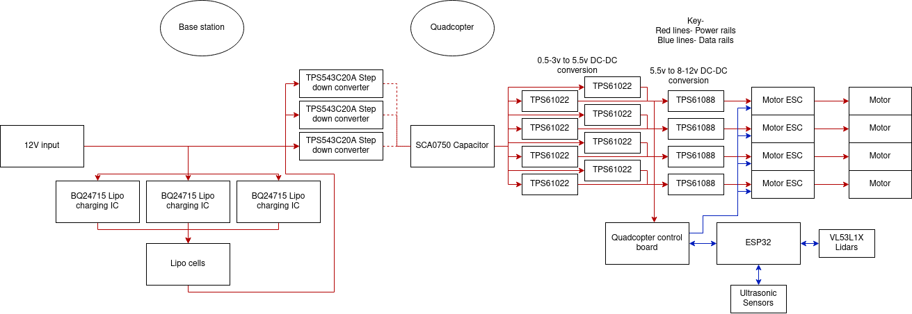
The next area I looked at was power ICs. First of all for powering the Lipo cells, I needed something that could take an input voltage of around 12V (a common value for a high wattage AC adapter) down to a safe voltage to charge the cells. After searching around, I found the BQ24715 by Texas Instruments, each capable of doing 3 cells at 8A, allowing each cell to be charged at 2.6A, which is the charge rate recommended for the cells. I would need to utilize 2 of these. Next would be the use of a 3 step down DC-DC converter to provide the right voltage to charge the Supercapacitor, the TPS543C20A (These were used because of their high current capability). After this I needed a DC-DC converter to provide a set output voltage from the variable input voltage from the capacitor. A solution I found was the LTC3110 meant for Supercapacitors, allowing a very low minimum input voltage which would be beneficial (0.1V), but it's low maximum current output and high cost meant the total cost of using them would be high, and will outweigh the positive of such a low minimum input voltage. I later chose to settle with the TI TPS61022 which is still meant for Supercapacitors with a minimum input voltage of 0.5V. The output current would still be too low, but utilising multiple of these would sort that, and costing just over $1 each meant they were good value. The TPS61088 could then be used to power the motors at 7.4V from the max output of 5.5V of the TPS61022. I calculated the total mass to be around 350g, so if the max output thrust from the motors is about 560 (350*1.6) then the power usage would be about 100W including the UV bulb (This is very close to the predicted power usage to enable 30 seconds of use time). Using 8 of the TPS61022 provides a max power of around 120W, allowing for some overhead in case it is necessary but also to aid longevity. The TPS61088 are able to provide around 30W of maximum power each, so using 4 is what would be necessary. I did calculations for the TPS61022 on its power output based on input voltage, as a lower input voltage would require more switching from the IC.
For sensor usage, I have had a look at time of flight sensors, which can be used as a Lidar. I found the recently released ST Microelectronics VL53L3CX. Although it has a lower measurement distance than some ToF sensors on the market, it can distinguish between different objects which could be very useful, that used in cognition with an extra algorithm could be used to work out if someone goes into a room. The idea was that two would be mounted, one on the top and the other on the bottom of the drone, being able to rotate within half a sphere, giving almost 360 degree vision. I am also thinking about the use of several ultrasonic sensors, to provide constant data from the main axis, which could also be used to compare values with to make sure of its accuracy.
As mentioned before, the base station will aid in air sanitization. I had originally planned for extra bulbs to be within the docking station, the issue with this is that it added to the cost and complexity. Also it shouldn't be taken as a full replacement for an air sanitizer, as it would not have the same power. Instead using the bulbs on the quadcopter itself, which I plan to rotate via motor for better access to surfaces, can sit within an air channel, which has the air passed through by the rotors acting as fans. This instead allows for the UVC bulbs to still take effect when while it is docked, without adding much to the cost. This makes the occasional charging less of a negative, as the product is still doing it's role.
Regarding tracking and replacement of bulbs, I think there could be two number LCDs which provide a percentage of the estimated life of the battery remaining. I think cause the use of hours could cause confusion and seem to pose a higher accuracy, when the life time given for bulbs is an average anyway. An app could also provide details on the amount of time the bulbs have been powered for. It will use some flash memory in order to do this. Because keeping hold of this information is very important, it will both use a secondary flash memory as well as an micro SD card port to export data. It could possibly use a comparator to check whether the original flash memory is still working. The micro SD card could be linked to the base station, so that the drone doesn't have to be handled too much. I am looking at using NOR flash as it has less room for error compared to NAND and is easier to use as well as having less pins while tending to have more write cycles. I am looking to use Micron memory as it is a well
known and reputable brand!
Is it safe? Ability to avoid damage, withstand damage and shutdown from humans-
Usage of both ultrasonic sensors as well as time of flight Lidars should mitigate most collisions. Withstanding damage- covers around the rotors, since while running they are susceptible to damage. Also use some kind of suspension system for the main body enclosure, like small springs to limit the impact of a fall. Also potentially having motors connected to the arms of the quadcopter, if it senses that it has gone upside-down, it can rotate the motors to push it upwards. It will also utilise more than one gyroscope and accelerometer to have a better idea of how it is flying, to help mitigate issues. For safety of others- while docked, a rubber seal between the quadcopter and base station should prevent light leaving, possibly a light sensor which could avoid over exposure on high reflectivity surfaces, a microphone and speaker to detect and warn people, with an auto cut-off of the Bulbs.
When motion is sensed, does exposure remain under the TLV (Threshold Limit Value) before the UV source shuts off?
Using Bulbs, the cut-off should be pretty quick, so yes is the answer.
Is the robot fully autonomous when UV irradiation is being performed?
Yes the idea is that it can be used autonomously, with the utilisation of a supercapacitor for powering the quadcopter, it will not need to be checked on for charging. Also since the charging is aided through magnets (potentially electromagnets), a user will not need to unplug the quadcopter. The base unit can either be plugged into the mains, or use its batteries.
Can the robot deliver a UV irradiation kill dose reaching of 25mJ/cm^2 in five minutes or less within six feet?
This would be achievable
Does the robot have full 360-degree movement?
Yes, and to some extent along all three axis.
Is data generated for sanitized spaces and lamp bulb life? Can the unit operate for long periods of time without charging? Can batteries be easily swapped out when depleted? (Please specify mean time between charge)
I would need to do more work looking into the software side of things, but with the utilisation of a range of sensors, data should be able to be generated about the spaces that are sanitized. There will be two number LCDs to give a rough percentage of bulb life remaining and have data stored both on flash as well as a microSD card. Although the quadcopter part of the product will technically be charged frequently, in regards to user charging it will not need to be recharged. I will allow for a method to do so though, in-case the base station cannot be used. With the base station plugged in, it can have continual use, where if used portably, it should hopefully get around an hour. I am hoping to do a design that allows for easy replacement of components, as it is better for longevity and is better environmentally. I will need to come up with a mean time between charge for the base station.
Are the UV bulbs protected from collision damage?
The bulbs would be enclosed in a clear plastic enclosure which would be supported with a small suspension system connected to it to help reduce an impact force.
Is the robot expected to be durable and relatively maintenance free? (Were quality parts chosen for the design?) (Provide proof of quality of parts)
It should be yes, with the implementation of things I have spoken about above. I am attempting to choose reputable parts, with good documentation or things I could potentially test. With most of the parts decided, this still stands true, using parts from companies such as Texas Instruments, ST Microelectronics, Skeleton Technologies and SunnySky motors.
Is it small and maneuverable? Can it maneuver in standard bathrooms? (consider stall doors (2ftx2ftx6.5ft WxLxH)?
Certainly, it has been built with these key features in mind. The width and length aren’t too much under this though.
Is it designed to be manufactured using readily available components and software? Does it use a minimal amount of custom components and software?
Yes I looked to use parts that are currently available, but to design a custom and complete circuit board. Depending upon time constraints, I may use a mix of open source and custom software.
Is the design cost-effective and quickly manufactured? (Provide reasons/documentation)
With the max budget that was set for the competition, my project should certainly be cost-effective. I am also planning to design different enclosure versions such as an injection moulded one, a 3D printed one and a Laser cut one. The designs will be readily available and I will look at using parts which can be sourced easily and will continue to be manufactured for a while.
Does the Bill of Materials (BOM) total less than 10,000 USD?
Easily! It is looking that the price should be around $200-300.
Is the documentation easy to follow, aiding in the manufacturing process?
A documentation document would be useful which showcases final decisions.
Are the building materials (including required software), readily available in quantities enabling volume manufacturing?
The components I have picked should fit this category, but I will send emails to make sure.
Does the design implement new ways of doing things? Does it proving efficiency, effectiveness, manufacturing, or drive costs down?
My design does implement a few new ways of doing things. A dockable robot which utilises its base for quick charging through the using a super capacitor instead of a lipo cell. I do not think that rotatable quadcopter arms have been used commonly, as well as using the quadcopter to provide extra air intake while charging shows efficiency. What I have came up with should hopefully be cheaper than most other solutions, partially helped by developing a product from the popular drone industry.
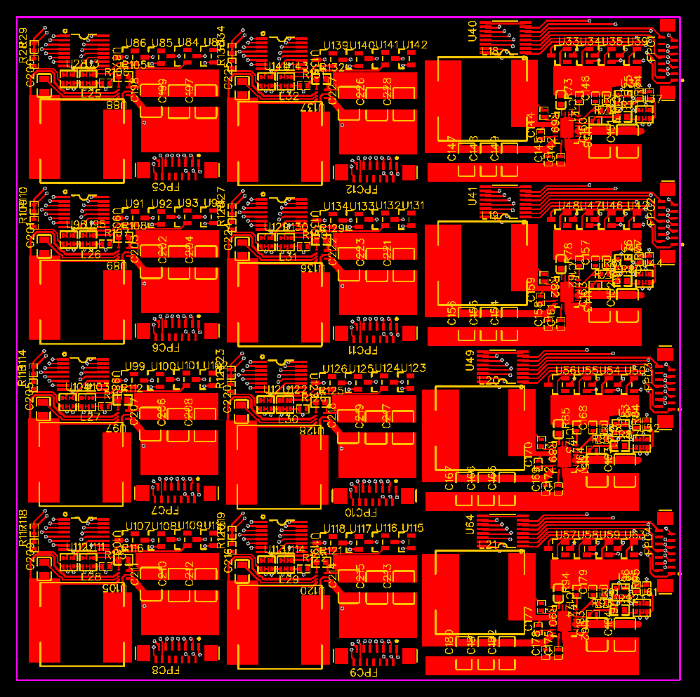
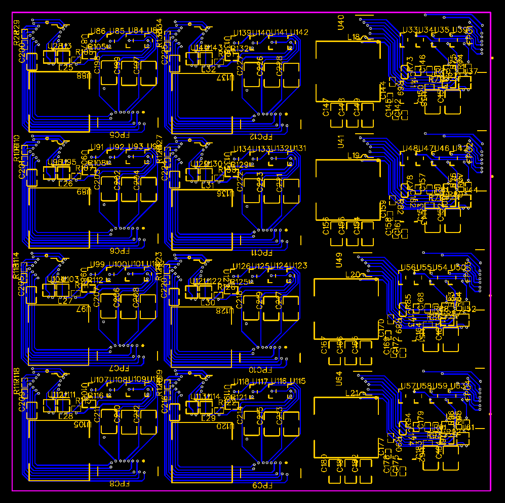
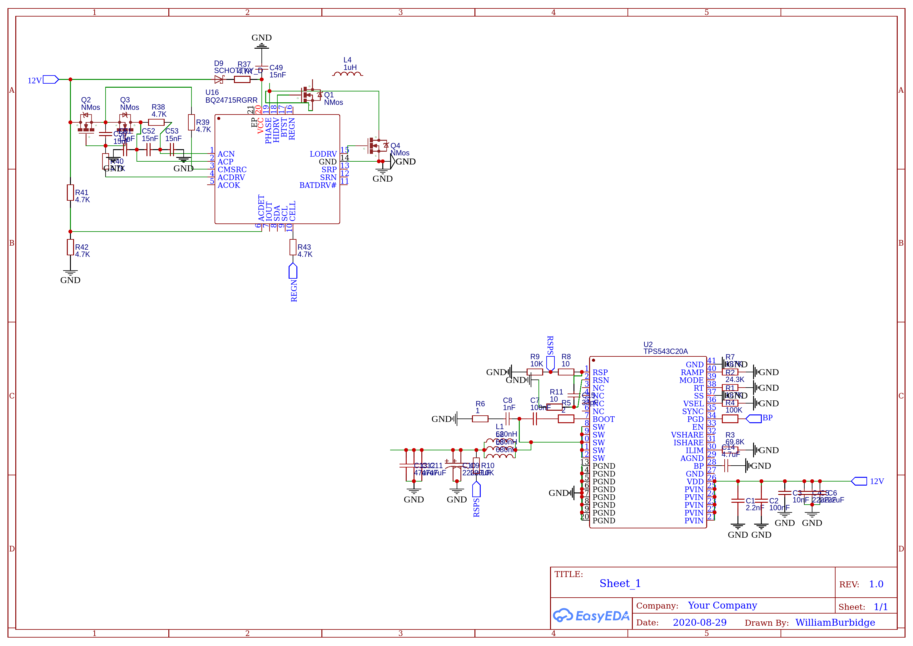
The above schematic shows the main components utilized in the design of the project. It doesn't have all the planned components but gives an overview of the workings of the PCBs.
Specific design decisionsThis section of the document talks into more detail about specific decisions I have made throughout the design. It will touch on the questions answered above
Electronics component usage
When looking at the electronics side of the product design, there were several steps I took so that the end product is the best it could be.
First of all was picking reputable and easy to source components. Picking components known for their quality should hopefully reduce the chance of finding quality control issues and should allow for longer and more stable longevity. When I say easy to source, this was looking at multiple factors. Firstly for more specific components such as specialised ICs, I picked larger companies which are stocked by major distributors such as Arrow, Mouser and LCSC, considering the original date of release so that it would continue to be manufactured for a while after design completion. Whereas for passives or more standard components such as resistors, I picked ones which were by well known manufacturers in that area as well as ones in a common footprint, rather than a less common or proprietary footprint design.
Next, I looked at picking parts over the minimum specifications for the use case. So on factors such as max current capability, I tended to use parts which are safely above the products requirements, to allow for longer usage. I also considered component tolerance against cost. Components such as resistors, capacitors and inductors were set to allow for higher power or voltage than required in case of a surge of current or voltage.
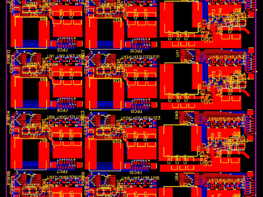
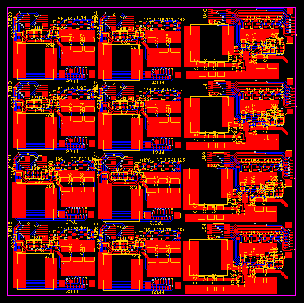
For the circuit board design, I wanted to come up with a design that could easily be copied, even for very low quantities. Therefore, the circuit boards I designed were two layer boards meant for 1oz copper layers. I also only had components on the top layer to allow for easy SMD soldering. The dimensions of each PCB have also been kept within 10x10cm as this is a common prototyping size, and is on the larger end of what could be placed onto a drone of the size class I had picked.
When considering the motor I needed to consider its weight, efficiency per watt and thrust as well as other smaller factors. The main thing I considered was the efficiency per watt. This is since the largest current draw will be from the motors, so making sure this is as efficient as possible was important. I picked a company well known amongst drone hobbyists as one of good quality and decent value.
Load sharing of the DC-DC converters
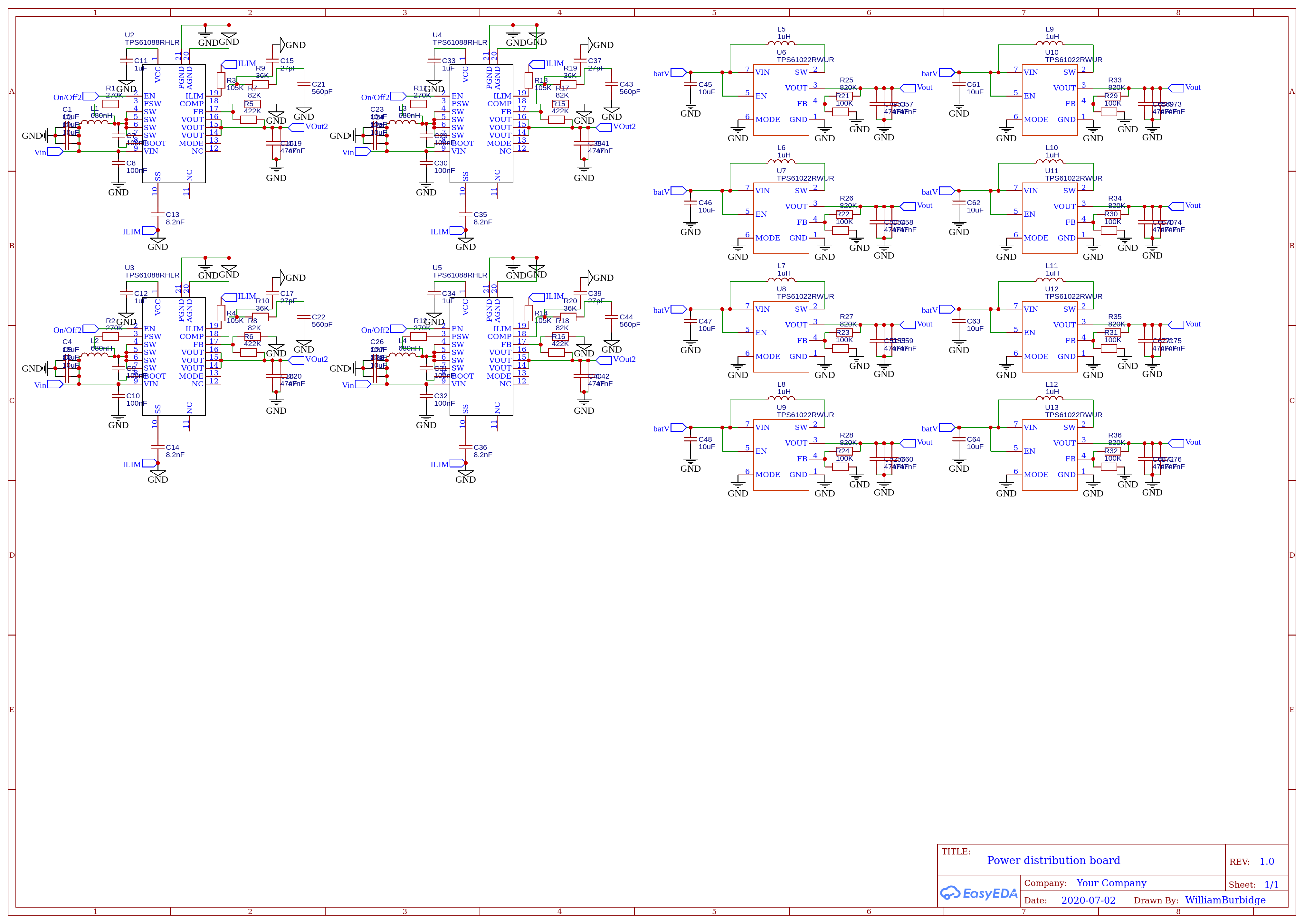
One issue regarding the electronics which needed solving was the issue of using DC-DC converters in parallel. The main issue with this is that they do not share a current load equally. Because of manufacturing defects there is a slight tolerance (of around 5% for the DC-DC converters) which the output voltage could lie between. This means that the converters which are at the higher end of this will also provide most of the load comparatively, reducing the efficiency of the circuit and decreasing the longevity of the higher load baring converters. I had a look at load sharing ICs currently, but they were both costly and mostly required a feedback pin which the converters I was using didn't have. Therefore I came up with my own solution. Something that could be altered for the ICs is their output current. This was based upon a ratio between two resistors. The idea I came up with, which can be seen in the PCB and schematic design, was to use a chain of resistors where utilising transistors, the path could be switched straight to ground from any one of the resistors. This allows for 5% voltage alteration either side of the target output voltage. This covers the predicted output voltage tolerance of around 5%. This switching is controlled by an external microcontroller on the main control board PCB.
Although the main programming wasn't complete, I began to write a Unity simulation for individual elements of the program.
This included a script to go towards set coordinates as well as to stabilize the drone, simulating movement based on 4 rotors. The idea was after each return to the charging dock, it would go to the next closest point and continue to do that until it needed to return to the dock again.
The other main script looked at the programming for the Lidar sensing, moving in 20 degree intervals along 2 axis for a total of 81 separate scans.
The individual elements which have been done so far are attached to this project, although some of which are not fully complete.
The main elements not completed were the PCB routing, programming and CAD design. The Power distribution board is pretty much complete, although could do with improved routing, the computation board wasn't completed and the base station board schematic was semi-completed. I had began to calculate values for the battery IC but didn't complete them. These have been quoted below and were quickly written ideas-
I am having to use an example footprint to assign names to pins for the TPS543C20A. To simplify the design and to improve the longevity of the batteries, I could just use two of the above so current and voltage can be shared, I think I will try and stick with 3. When selecting the inductor, it is a custom part wrote down which I cannot find one which fits those parameters (current wise). Therefore I am going to use multiple in series, which add up to the right inductance and current capability. It looks like it would be better to have three equal ones in parallel, using the formula. Therefore 3 at 680nH seem to be the best choice. This should also help to decrease the resistance too.
For the BQ24715RGRR, I need to quickly use the datasheet to decide on components to use. First thing is to decide on an inductor to use. D = vout/vin, minimum vin = 9v. So I will have input of 12.6V.
Switching frequency choices are 600, 800 or 1000kHz, I will test values of each using the equations from the datasheet.
D = 9/12.6 = 0.7143
Therefore (12.6 * 0.7143 * (1-0.7143)) / (800000*L) goes to 2.5713 / 800000 * L
Inductor ripple is designed to be between 20 and 40 percent size of max charge current. With max charge current of about 8A, I will look at 30 percent first.
8*0.3 = 2.5713 / (800000*L)
2.4L = 2.5713/800000
L = 0.000001339 which is 1.339uH.
Isat = 8 + (2.5713/800000*0.000001339) = 10.4A
I will see what kind come with these values in mind. I will then look at the difference with 1000kHz and 600kHz. 1.2uH is the closest.
When it = 1000kHz, then 2.5713/1000000*L
2.4L = 2.5713/1000000 = 1.071uH, then I can use a 1uH inductor.
When it = 600kHz, then 2.5713/1000000*L
2.4L = 2.5713/600000 = 1.786uH, then I can use a 1.8uH inductor, but I couldnt find many with higher current capability.
I will use a 1uH and will go with the 1000kHz, as I have found a low resistance inductor with a good current capability.
C380067 LCSC part No
If I was to do the project again, I would have done things differently, the main one being the time management of the project. I would have liked to focus more on the physical design rather than the concepts. I feel the feature set of the product fits a gap in the market well, I would need more time though to fully develop it. This has lead to some parts not being finalized such as the PCB routing, programming and CAD design. I am hoping to continue this project though until it is a fully functional product idea.
Here are links to premade parts which can be utilized along with what has been designed, these are also listed in the parts list above-
Quadcopter frame 250mm- https://bit.ly/3gJIYBu
Ardupilot board- https://bit.ly/3jwjuJA
Motor ESCs- https://bit.ly/3lv2Z2p



Comments