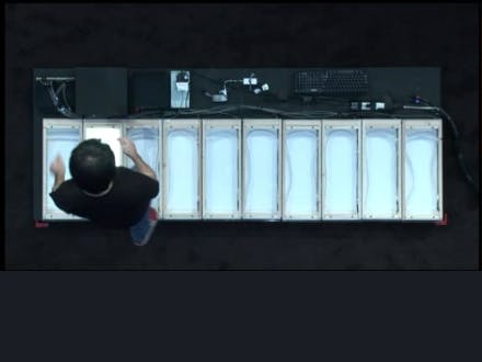
//build 2014 - Piano
This how-to demonstrates the basic wiring of the big piano featured at the 2014 //build conference. The piano was demoed on stage during Terry Myerson's keynote speech by Joe Belfiore. This project will illustrate how to recreate a breadboard version of the original Windows IoT hack!
Hardware
This project will be a little easier on the pocket book than the original. Now with Windows 10, we can replace the big ticket items (the Galileo and the SparkFun MP3 Shield) with the Raspberry Pi 2. Then, assuming you can scrounge up a generic USB keyboard, the only part you may have to plan for is the MCP23S17. Otherwise, you should be able to shake all the rest of the parts out of your toolbox. So grab a handful of tactile buttons, wires, LEDs and resistors, and let's get ready to hack!
If you don't have fourteen buttons laying around, don't worry about it. The software is built for fourteen keys, but it works just as well with less.
Breadboard:
The construction is mostly straight-forward. Place the MCP23S17 on one end of the breadboard and the buttons on the other side. It is important to layout the buttons, because they will be a forcing function for spacial considerations. The buttons are three holes wide and they each have four legs with a free space in between (this is important, because we will run the resistors for the lights underneath the button between its legs).
Now that you have it all laid out, hook wires from the A and B ports of the port expander (MCP23S17) to one leg of the resistors bridging the center gap of the breadboard. Then place the LED's anode (positive or long leg) on the other end of the resistor, and the LED's cathode (negative or short leg) in the negative gutter on the side rail. Finally, set the buttons over the top of each resistor.
Keyboard:
The keyboard is actually the easier of the two, but it requires a little soldering. Most keyboards are matrix keyboards, which means button presses are registered when a connection is made between two axes. You can test how your keyboard is wired by plugging it into your computer and shorting different pads to what it types on your screen. Then you can solder leads onto the most productive pads (shown above). Simply wire these leads into the breadboard, so the tactile buttons create the shorts and, viola, you have a brand new keyboard. Once you have determined which keys you have available, be sure to update Assets\KeyMap.xml to ensure those keys are active and assign sounds to play when they are pressed.
What's with the odd characters? I thought you'd never ask! XAML deals with the keyboard via VirtualKeys. To over-simplify for the sake of brevity, imagine there is a single character value for each button on the keyboard. Therefore when you see a punctuation character written on the key, there may also be (and likely is) an actual character hiding underneath it; this behavior has to do with Unicode. If you run this application in Debug mode, you will see the letter (printed in the right-most black key) the application is receiving as VirtualKey input. Then you can simply copy and paste the same character from this Unicode table into your XML file.
Let's make some noise!
Don't Forget!
Windows 10 is UNIVERSAL, so you can download and build this project for ANY Windows 10 device! However, if you have a Raspberry Pi 2, then you can build your own keys, and that's where the real fun starts...


_3u05Tpwasz.png?auto=compress%2Cformat&w=40&h=40&fit=fillmax&bg=fff&dpr=2)
Comments
Please log in or sign up to comment.