


Hardware components | ||||||
_ztBMuBhMHo.jpg?auto=compress%2Cformat&w=48&h=48&fit=fill&bg=ffffff) |
| × | 1 | |||
| × | 1 | ||||
Software apps and online services | ||||||
 |
| |||||
What is LoRa
LoRa (Long Range) is a widely used wireless technology for the Internet of Things (IoT).It excels at long-range communication, reaching kilometers in rural areas, compared to Bluetooth or Zigbee. The trade-off is that data transmission speeds are slower.LoRa itself is a radio communication technique, while LoRaWAN is the network protocol that works on top ofLoRa protocol. This combination is ideal for battery-powered sensors that infrequently transmit small amounts of data, like monitoring environmental conditions or tracking assets.
LoRa communication has multiple frequency options. It is recommended that you choose your device's frequencies according to your region.
433 MHz (Asia)868 Mhz (North America)915 Mhz (Europe)
The LoRa node RN2483 can communicate on both 433 Mhz and 868 Mhz.
Find out more about frequency plans. https://www.thethingsnetwork.org/docs/lorawan/frequencies-by-country/
There are two methods of communication with LoRa
- LoRa peer-to-peer communication.
- LoRaWAN.
We will discuss both of the methods in this article.
Overview of the ModuleThis LoRaNODE offers the full capabilities of Microchip RN2483 as a ready to use module which the user can not only plug connect the module to his microcontroller or the device but also connect to the PC (Using an Onboard micro USB Connector) for testing and debugging purposes. In addition, each LoRaNODE comes with two Antennas for 433MHz and 868MHz, So that is a fully easy-to-use kit not only for hobbyists but also for experienced developers.
General Features
- PCB Dimension : 3.8cm x 6.4cm
- On-board MicroUSB socket for Debug and testing
- On-board interface for external MCU interfacing (Logic level:3.3V)
- All pins of RN2483 can be accessed via the pin headers
Microchip RN2483 General Specifications
- Type: Sub-GHz
- Power Output: 14 dBm
- Temperature range: -40°C to +85°C
- Interface: UART
- Pin Count: 47
- RF Module : Yes
- RF Transceiver: Yes
- Frequency Range: 434, 868 MHz
- Input Sensitivity : -146 dBm
- TX Current Consumption: 40 mA (14dBm, 868MHz)
- RX Current Consumption : 14.2 mA
- Operating Voltage : 3.3V DC
Microchip RN2483 Operational Data
- On-board LoRaWAN™ Class A protocol stack
- ASCII command interface over UART
- Temperature range: -40°C to +85°C
- Programmable RF Communication Bit Rate up to 300 kbps with FSK modulation, 5468 bps with LoRa™ Technology modulation
- Integrated MCU, Crystal, EUI-64 Node Identity Serial EEPROM, Radio Transceiver with Analog Front End, Matching Circuitry
- 14 GPIOs for control and status
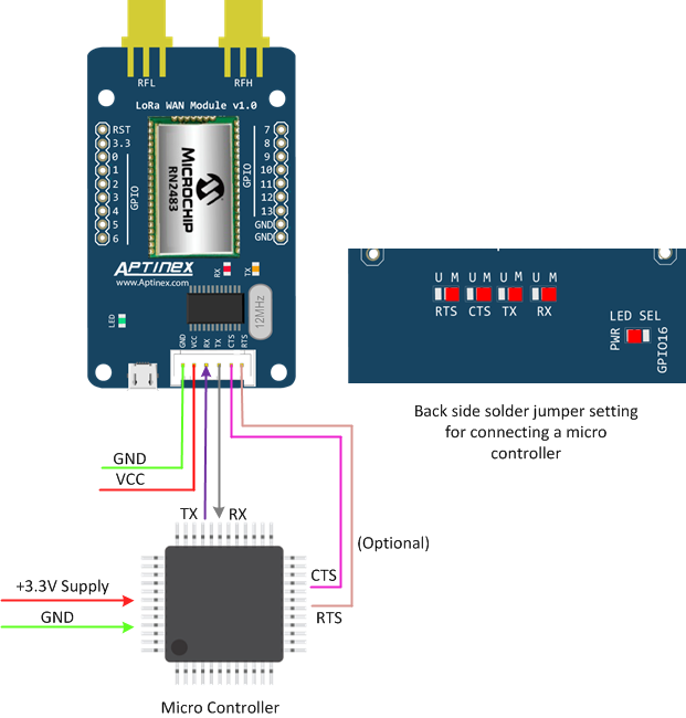
To begin with the module you need to set the solder bridges that determine communication with the module. This module communicates over UART. It would be either direct USB communication with the computer or hooking up an external microcontroller (Arduino in this article) via UART.
1.Direct communication with PC over USB Serial.
In this case, UART will converted to USB via an onboard transceiver chip
2.RN2483 connecting directly to a microcontroller.
This solder bridge configuration bypasses the UART to USB transceiver chip and directly connects to the microcontroller via its UART interface.
Once that is done, the module is ready for the first example.
Example 1 - Peer-to-Peer Communication.In this example, I’ll show you how to send a message or receive LoRa messages via the RN2483 module. First we will use communication with the module via the USB serial method.
First, connect the module via USB to the computer. Then open the serial monitor of the Arduino IDE(or any serial monitor application), set the baud rate to 57600, and select the “Both NL and CR” option.
Note:- In the Arduino serial monitor baud rate 57600 won't appear on the dropdown menu for boards such as Arduino UNO. Try selecting another board type.
Now to test the device send the command
sys reset
If the response is similar to below module is up and running so we can proceed with AT commands
RN2483 1.0.4 Oct 12 2017 14:59:25Note:- if your serial program doesn't have NL and CR option try adding <CR><LF> suffix to each command
Eg:- sys reset<CR><LF>
There are three types of commands for this module
- System commands ( start with “sys” )
- Radio commands (start with “radio” ) - Handles settings with data transmission over LoRa or FSK
- Mac Commands (start with “mac” )- Handles configurations for LoRaWAN
RN2483 Command Manual - https://ww1.microchip.com/downloads/en/DeviceDoc/40001784B.pdf
Now let's transmit over the LoRa protocol
Connect the antenna to RFH(868 MHz) connector. The module supports both 433Mhz and 868Mhz bands. For this example, we will be using the868.1 MHz band since it's the default frequency.
There are multiple parameters to set up for LoRa transmission. For simplicity, we would use default settings to transmit without changing them.
Additional information:- Default radio settings of RN2483
- Frequency - 868.1Mhz
- Spreading Factor - 12
- Watchdog timer - 15000
- Bandwidth - 125KHz
- Preamble Length - 8
- Coding Rate - 4/5
Receiver Commands - preparing module for receiving the data packet.
radio set wdt 0
mac pause
radio set sync FF
Radio rx 0
Transmitter Commandsradio set wdt 0
mac pause
radio set sync FF
radio tx FFFFFFFF
“radio set sync 05” - to set the sync word. In this case, sync word is 0xFF so the module only receives LoRa transmissions with the sync word 0xFF.
“radio tx FFFFFFFF” - a hexadecimal value representing the data to be transmitted. Here the data is FFFFFFFF.
If themessage received successfully “radio_rx FFFFFFFF” will display on the serial monitor.
Now let's do the same with Arduino.
RN2483 Module ---------------> Arduino
GND--------------------------------> GND
VCC--------------------------------> 3.3V
Rx----------------------------------->11
Tx-----------------------------------> 10
Transmitter Code
#include <SoftwareSerial.h>
// Define the SoftwareSerial pins
const int rxPin = 10;  // RX pin to Arduino (connect to TX of RN2483)
const int txPin = 11;  // TX pin from Arduino (connect to RX of RN2483)
// Create a SoftwareSerial object
SoftwareSerial loraSerial(rxPin, txPin);
// Function to send a command to RN2483 and print the response to Serial Monitor
void loraSendCommand(String command) {
while (loraSerial.available()) {
loraSerial.read();
}
// Send the command to the RN2483 module
loraSerial.println(command);
// Wait for a response
String response = "";
unsigned long timeout = millis() + 5000;  // 5 seconds timeout
while (millis() < timeout) {
if (loraSerial.available()) {
char c = loraSerial.read();
response += c;
// Check if response ends with "\r\n"
if (response.endsWith("\r\n")) {
break;
}
}
}
// Print the response to the Serial Monitor
Serial.println("Response: " + response);
}
void setup() {
Serial.begin(9600);
// Initialize software serial for RN2483 communication
loraSerial.begin(57600);  // Default baud rate of the RN2483 is 57600
Serial.println("LoRa RN2483 Communication Setup");
//  initialization commands to configure the RN2483
loraSendCommand("sys reset");
delay(100);
loraSendCommand("radio set wdt 0");
delay(1000);
loraSendCommand("mac pause");
delay(1000);
loraSendCommand("radio set sync FF");
delay(1000);
}
void loop() {
// Send the message "FFFFFFFF"
String messageToSend = "FFFFFFFF";
Serial.println("Sending Hex Message: " + messageToSend);
// Send the hex string
loraSendCommand("radio tx " + messageToSend);
// Wait for a while before sending the next packet
delay(20000);  // Send data every 10 seconds
}
Receiver Code
#include <SoftwareSerial.h>
// Define the SoftwareSerial pins
const int rxPin = 10; // RX pin to Arduino (connect to TX of RN2483)
const int txPin = 11; // TX pin from Arduino (connect to RX of RN2483)
// Create a SoftwareSerial object
SoftwareSerial loraSerial(rxPin, txPin);
// Function to send a command to RN2483 and print the response to Serial Monitor
void loraSendCommand(String command) {
// Clear any previous data in the buffer
while (loraSerial.available()) {
loraSerial.read();
}
// Send the command to the RN2483 module
loraSerial.println(command);
// Wait for a response
String response = "";
unsigned long timeout = millis() + 5000; // 5 seconds timeout
while (millis() < timeout) {
if (loraSerial.available()) {
char c = loraSerial.read();
response += c;
// Check if response ends with "\r\n"
if (response.endsWith("\r\n")) {
break;
}
}
}
// Print the response to the Serial Monitor
Serial.println("Response: " + response);
}
// Extract the message part from the response
if (message.startsWith("radio_rx")) {
int startIndex = message.indexOf(" ") + 1; // Find the space after "radio_rx"
String extractedMessage = message.substring(startIndex);
Serial.println("Extracted Message: " + extractedMessage);
}
// Set the RN2483 module back to receive mode after receiving a message
loraSendCommand("radio rx 0");
}
}Understanding LoRaWAN
LoRaWAN is a network protocol that built-in top of the LoRa protocol.
LoRaWAN allows LoRa-equipped devices such as sensors to communicate with a network server. Unlike devices with WiFi or Ethernet connectivity, these devices cannot communicate to theinternet or cloud directly. To help with that LoRa gateway is needed.
LoRaWAN utilizes gateways, and base stations that act as bridges between nodes and the network server. Think of them as regional radio towers that collect messages from nearby devices and forward them to the central hub.
This way the node sends and receives encrypted data directly to the server through the gateway. A gateway can be configured to work in different modes. The simplest way is to use it as a packet forwarder. The gateway I am going to use in this tutorial is RAK7268. This gateway supports working on both basic station mode and network server modes.
The most popular LoRaWAN network server is ThethingsNetwork.com.However for this tutorial I will be using Chirpstack.
Both platforms allow you to visualize the data from the nodes easily.
Before beginning with LoRaWAN with RN2483 Module you must have an idea of LoRaWAN basics such as frequency bands, LoRaWAN classes, and network joining methods.
Frequency Bands
- EU868(Europe)
- US915(United States)
- AS923(Asia)
- AU915(Australia)
- IN865(India)
The RN2483 supports EU868 bands.
LoRaWAN End Device (Node) Classe
- Class A: communication is initiated only by the end device. Downlink messages from the network server are queued until the next time an uplink message is received from the end device which starts listening for downlink messages shortly after.
- Class B : Listens to downlink messages from the server at specific intervals.
- Class C : Listens to downlink messages all the time unless transmitting an uplink
Note:- Uplinks means messages from the end device to the network server through the gateway. End devices(Nodes) can't transmit and receive at the same time.
RN2483 supports all 3 classes but in this article, we will try out with class A.
Before an End Device(Node) transmits and receives data on a LoRaWAN network it must join the network. This activation process is very important since the module will only transmit data if the joining process is successful. There are two joining methods. Over-The-Air-Activation (OTAA) and Activation By Personalization (ABP)
Over-The-Air-Activation (OTAA)
In order to OTAA, we must give 3 important pieces of information to the module.
- DevEUI - a 64-bit unique ID for the end device(RN2483). This ID is assigned to each LoRaWAN device by the manufacturer just like MAC for WiFi-enabled device
- App EUI/Join EUI - Identifier for application created on the network server. This ID binds our LoRa device to the specific application.
- AppKey - Security key key for encryption of data. This key is unique for each end device(node).You can easily get the DevEUI of the RN2483 by sending the necessary command.AppEUI and appkey can be retrieved from Thethingsnetwork or ChirpStack while adding the application and the device profiles.
First, the end device will send a join request message then if there is a matching application on the server it sends back the join Accept message containing Device Address (DevAddr), Network Session Key (NwkSKey) and Application Session Key (AppSKey).
The next method directly inputs those necessary data into the end device bypassing the communication with the server.
2. Activation By Personalization (ABP)
The following information must be configured in the module to join the network.
- Device Address (DevAddr) - A fixed address assigned to the device for communication within the network
- Network Session Key (NwkSKey) - A shared secret key used for encrypting application-specific data payload in uplink messages.
- Application Session Key (AppSKey) - A shared secret key used for encrypting downlink messages from the network server.
Note:- Do not confuse Appkey with AppSkey(Application Session Key). Those are different keys.
The OTAA method is more secure than the ABP method.
Before connecting with RN2483 to the TheThingsNetwork or ChirpStack you need to connect your gateway to your preferred network server and then create an application for your node to communicate thus receiving the necessary keys for the activation. I will use Chirpstack for this example you may use TheThingsNetwork for this. If you are a beginner I recommend doing that with TTN(TheThingsNetwork). If you prefer more customizability, you can use ChirpStack which is open-source.
Run Chirpstack local server: https://www.chirpstack.io/docs/getting-started/docker.html
https://github.com/chirpstack/chirpstack-doc
Registering your Gateway with ChirpstackSee also - Register your Gateway with TheThingsNetwork-https://www.thethingsnetwork.org/docs/gateways/registration/
Once chirpstack is up and running log into it from the browser. Go to the gateways tab then click add gateway. All you need to enter is GatewayEUI and a name. Gateway EUI is unique for each gateway. You can get it from the web interface of the device or it may be imprinted on the device.
In order to connect to a particular LoRa network server, the gateway should be given the following information.
Server address
Server port (typically 1700)
Before connecting the LoRa Node to the chirpstack you must add the device and create an application within the server. This step is where we retrieve various keys that I mentioned above to establish a connection with the ChirpStack.
Setting Gateway Radio SettingsThe module supports the EU868 band. Obviously you need to set the gateway's frequency band to EU868. That frequency band communicates via 3 channels.
Receiving (downlink) frequency is called as RX2 frequency.Rx2 frequency for EU868 is 869.525MHz.
The above channels and Rx2 parameters tally with the default values of the module. Please note that the above channel 1, 2, 3 frequency and SF values cannot be changed.
In EU868 LoRaWAN, RX1 delay refers to the waiting period an end device observes after transmitting an uplink message before opening its first receive window (RX1) to listen for a potential downlink response from the network server.RX1 is 100ms
The default RX1 delay for the module is 2000ms.You can set it to 1000ms by “mac set rxdelay1 1000” command.
see AT command module documentation for more details.https://ww1.microchip.com/downloads/en/DeviceDoc/40001784B.pdf
To communicate those parameters must tally with gateways radio settings.
Creating an application and adding a device to the ChirpStack.First, we must create an application to add a device.(an RN2483 node).In the WebUI go to the Application tab then click Add Application.
Give your application a name and click submit.
The next page will allow you to add devices to the application that you have created. But before that, you must create a device profile with the configurations for RN2483.
Go to the Device Profiles tab and click Add Device Profile. This page will allow you to add configurations for the RN2483. Enter the configurations indicated in the below.
Note:- The LoRaWAN MAC version is determined by the current firmware version included in the RN2483 chip. The firmware version is displayed in the serial monitor following the command “sys reset”.I am currently using a device shipped with firmware Version 1.0.4 which is compatible with specification 1.0.1.
Once the device profile is created now move into adding devices to our application in the ChirpStack.
Go to the application and click Add New Device.
Device EUI (EUI64) - As I explained before this is unique for each LoRaWAN hardware. You can get your DevEUI by sending the serial command “sys get hweui”.
Join EUI/App EUI - click the generate button to create a random Join EUI. Note down the EUI since it will be needed when connecting to the LoRaWAN network.
Click submit then go to OTAA keys. In this tab, you can set Application keys(AppKey). Generate keys and click submit.
Now you have all 3 keys needed for OTAA activation with the chirpstack.
Example 2 - LoRaWAN with RN2483 NodeWhen you are done with setting up the LoRaWAN server and gateway let's configure the module.
First, we will activate the device using the OTAA method and then send data packets to the server with RN2483.
The following commands need to be sent to the module in order for OTAA activation.
mac set deveui YOUR_DEVICE_EUIEntering device EUI
mac set appeui YOUR_APPLICATION_EUIEntering join EUI copied while adding the device to the application.
mac set appkey YOUR_APPLICATION_KEYEntering application key
mac saveSaving the parameters to the onboard EEPROM or otherwise, we would have to enter those data again after a power loss or module reset.
You will be able to read those data (except appkey) by sending AT commands to verify the keys you entered.
mac get deveui
mac get appeui
Joining the network.
mac join otaaIf the join procedure is successful the module will return “accepted”.
Please note that in order to join successfully you must configure gateway and ChirpStack correctly.
If the module returns “Denied” there are many possible causes,
- Gateway cannot receive uplink from the module. You must check theradio settings of the gateway.
Hint:- If your gateway has a packet logger it is possible to observe uplinks and downlinks between the server and the node. It includes details like frequencies, spreading factors, and packet types.
- Gateway forwards the packet to the ChirpStack but does not send a JoinAccept message. Chirpstack WebUI displays incoming as well as outgoing data packets on the gateway page. Click the LoRaWAN Frames tab. Even If the OTAA request is received by the server it could reject the request since it does not match any device and application you configured. In that case possible solution is to check if keys tally with each other. Chirpstack also rejects packets coming from frequencies other than the frequency band you entered while adding a new gateway. (These packets are not displayed in the LoRaWAN Frames tab)
- ChirpStack sends back a JoinAccept message to the gateway but the module cannot receive the downlink. Check the gateway packet logger to confirm whether the gateway sends the JoinAccept. If so check radio settings such as RX2 frequency, Rx2 datarate, and RX1 delay. Those are the radio settings associated with downlink.
Once OTAA is successful you can send data packets to the server.
There are two types of data frames for LoRaWAN.
- Unconfirmed Data - Just sending the data message. A confirmation is not required.
- Confirmed Data - Once the data frame is received by either the LoRaWAN server or the node it sends back a confirmation message that lets the sender know that the message was successfully received.
Command format
mac tx <message type> <port number> <data><message type> string representing the uplink payload type, either cnf or uncnf (cnf – confirmed, uncnf – unconfirmed).
<port number> decimal number representing the port number, from 1 to 223.
<data> Hexadecimal data value.
Sending unconfirmed data frame
mac tx uncnf 5 AABBCCDDEEFFSending confirmed data frame
mac tx cnf 5 AABBCCDDEEFFCheck the LoRaWAN frames tab on the gateway page whether the message is received.
If you have any questions or trouble with setting up the modules please free to comment below.


Comments