Experimental studies would assert the possibility that particulate matter may act as a “carrier” for the spreading of the viral infection of COVID-19.
This means that the virus could be carried over longer distances by fine particles suspended in the air and could remain viable for hours, days or even weeks in tiny particles. So, air pollution particles could help coronavirus travel further in the air, increasing the number of people infected.
In Northern Italy the lockdown didn’t produce a considerable reduction of particulate matter, because particulate matter is obtained in large quantity also by intensive livestock farms, besides factories and cars. So, even if during lockdown factories were closed and cars didn’t circulate, particulate matter concentration levels in Lombardy (Italy) remained high in any case, due to intensive livestock farms located in its territory that continued to produce manure, and therefore pollutants in the air, and among others, particulate matter.
Scientists and reserchers suggest that higher levels of particle pollution could explain higher rates of infection in parts of Northern Italy.
IntroductionA few weeks ago I watched an Italian TV programme called “Report”. It is an investigative programme broadcast on channel three (RAI 3) by the Italian television.
An interesting piece caught my attention…It was about pollution and in particular about a type of pollution caused by intensive animal farming. (Click here to see the corresponding part: from minute 27:25 to minute 56:00).
Intensive livestock refers to a system of farming in which large numbers of animals (such as cows, pigs, turkeys or chickens) are kept together into relatively small spaces. The aim is to produce large quantities of meat, eggs, or milk at the lowest possible cost. They are also known as “factory farms”.
Animals raised on overcrowded and factory-style farms generate a large quantity of animal waste, like urine and manure. Manure is generally stored in huge, open-air ponds, often as big as several football fields, which are prone to leaks and spills, polluting soil and contaminating water supplies. Animal waste also emits harmful gases into the atmosphere (such as ammonia, endotoxins, hydrogen sulfide and methane) and releases large amounts of particulate matter (PM10 and PM2.5; PM10 is the acronym for “particulate matter with diameter ≤ 10 µm”, PM2.5 is the acronym for “particulate matter with diameter ≤ 2.5 µm”), creating environmental problems. Particulate matter contains microscopic solids or liquid droplets that are so small that they can be inhaled and cause serious health problems.
When the cesspools reach their capacity, farmers spray the untreated manure onto surrounding fields as fertilizer, and that bring still more of these harmful substances into air.
Untreated waste pollutes the air with odors (the stench can be unbearable) and creates health problems, markedly decreasing the quality of life of workers, people nearby and neighboring communities and property values. Studies have shown that people who live near intensive livestock farms have a much greater risk of developing respiratory problems, such as asthma and chronic bronchitis.
In Italy most intensive livestock farms are located in the North of the country. Lombardy is one of the regions with the highest concentration of intensive livestock farms; consequently the quantity of excrement and animal waste produced in livestock facilities is very high and that generates large amounts of gases and particulate matter.
It should be noted that, in Lombardy 85% of ammonia dispersed in the atmosphere is produced by manure: it would seem that farms pollute in the same way as cars.
A study carried out by researchers from several Italian universities and published last March with the title “Evaluation of the potential relationship between Particulate Matter (PM) pollution and COVID-19 infection spread in Italy” (at the following link it is possible to download the Position Paper: https://www.simaonlus.it/?page_id=694 , direct link to the english pdf http://www.simaonlus.it/wpsima/wp-content/uploads/2020/03/COVID_19_position-paper_ENG.pdf - I recommend reading it!) speaks about a possible correlation between particulate matter concentration levels and the number of persons infected by COVID-19 (as you can see in the following diagram).
Researchers have collected and analyzed the following data:
- PM10 daily concentration levels (data provided by Regional Environmental Protection Agency - ARPA - and collected all over Italy);
- The daily PM10 limit value exceedances;
- The number of COVID-19 infected persons for each selected province, communicated by Civil Protection and updated with daily frequency.
and have noticed a significant relationship between the daily PM10 exceedances and the spreading of the COVID-19 infection during the time-lapse of the study (10th-29th February 2020), with a high concentration of Coronavirus cases in Northern Italy, in particular in the Po Valley and especially in Lombardy, while in Southern Italy the diffusion and lethality of the virus was significantly lower if compared with that observed in Northern regions.
In this position paper it is possible to read “The hypothesis of a direct relationship between COVID-19 cases and PM10 levels is strengthened by the evidence that concentration of COVID-19 outbreaks notified in Po Valley [in Northern Italy] was higher than in other parts of Italy” (as you can see in the following figure, that shows the exceedances of PM10 pollution limits registered in Italy in the period 10th February - 29th February and where it is possible to note that the Po Valley is the most polluted area in Italy).
It is very remarkable that most of the Coronavirus cases in Italy are located in Lombardy, where the concentration of intensive livestock farms is very high and the consequently production of particulate matter is enormous.
It should be noted that this phenomenon continued even during the lockdown, when factories were completely closed and cars didn’t circulate.
According to this study, in the Southern regions of Italy (less polluted) the prevalent pattern of viral transmission would be occurred by contact between people (in agreement with epidemic models based on the typical transmission mode ‘person-to-person contact’), whereas in the regions of Northern Italy (more polluted), the infection would be spread in a different way, that’s to say by a carrier agent (represented by the particulate matter suspended into the atmosphere).
The following infection expansion curves highlight the anomaly of Northern Italy in COVID-19 infection spread, compared with Central and Southern Italy.
On the basis of the collected data and observed relationships, researchers conclude by saying that it is reasonable to assume that, during the period 10th-29th February 2020, high PM10 concentration levels registered in specific Northern Italian regions had a carrier and boost effect to the virulent spread of the COVID-19 epidemic, promoting the diffusion the COVID-19 among the exposed population, phenomenon not observed in other Italian regions that were affected by the contamination during the same period.
Other studies have shown that PM would act as a carrier for viruses. Viruses, in fact, may attach themselves to particulate matter, whose small particles can travel long distances on air currents and remain in the atmosphere for hours, days or even weeks.
Particulate matter also would represent a substrate allowing viruses to remain active into the atmosphere for some time (hours or days). Environmental factors play an important role in activation and persistence of viruses in the atmosphere:
- High temperature and solar radiation speed up inactivity;
- High relative humidity may promote the diffusion rate.
A research has shown that virus survival on surfaces decreases when relative humidity is maintained around 50%, while viruses remain active when relative humidity values are below 40% and above 60%.
Another research from Yale University has shown how low humidity conditions allow infected particles to spread better and survive longer (click here to see the article).
My solutionOn the basis of these considerations, I have thought of creating a replicable, low cost and easy to use device able to measure PM10 concentration levels, temperature and relative humidity (environmental factors involved in viral infection spread), in order to warn people when these values are too high and potentially dangerous for their health, so they can choose to stay home and don’t go out or, if they are outside, to go home, or wear a mask, even if distances between people are much greater than one meter.
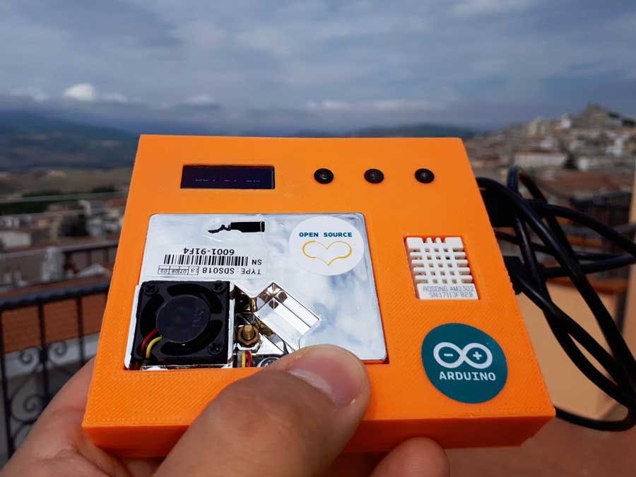
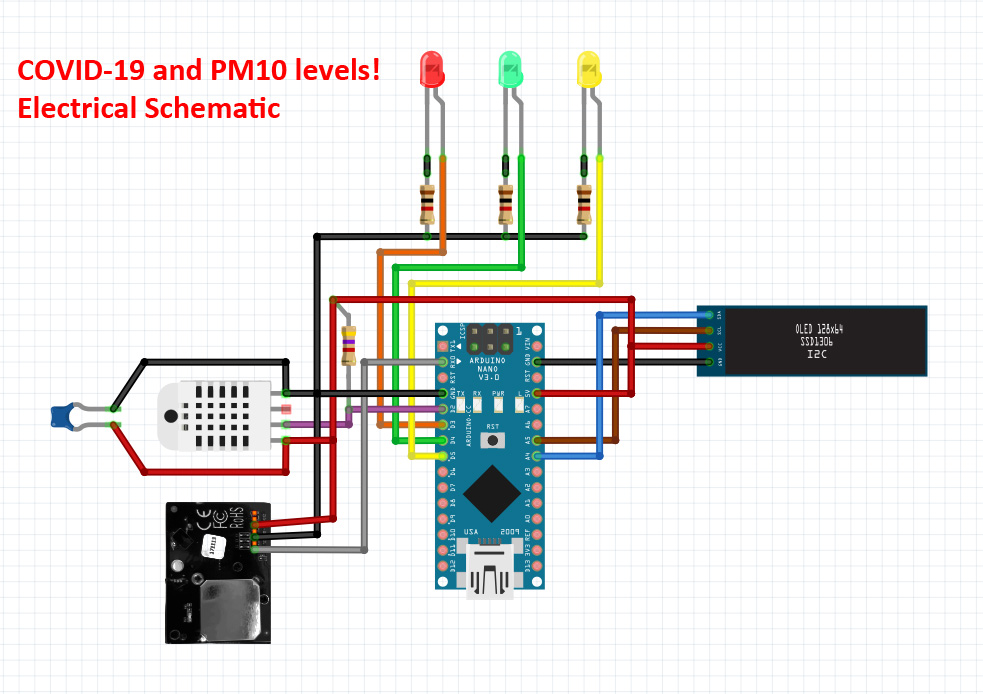
The device consists of a PM10 sensor, a temperature and relative humidity sensor, a display and three LEDs, all controlled by an Arduino Nano. The sensor data are shown on the display and the LEDs indicate what the air situation is.
I have identified four different situations:
1. Normal – Particulate matter concentrations from 0 to 25 µg/m3 and humidity between 40% and 60%;
2. Low - Particulate matter concentrations from 0 to 25 µg/m3 and humidity < 40% or > 60%;
3. Low - Particulate matter concentrations from 26 to 50 µg/m3 and humidity between 40% and 60%;
4. Warning - Particulate matter concentrations from 26 to 50 µg/m3 and humidity < 40% or > 60%;
5. Warning - Particulate matter concentrations > 51 µg/m3 and humidity between 40% and 60%;
6. Alarm - Particulate matter concentrations > 51 µg/m3 and humidity < 40% or > 60%.
Associated LEDs:
- Normal: LEDs OFF;
- Low: Green LED ON;
- Warning: Green and Yellow LEDs ON;
- Alarm: Green, Yellow and Red LEDs ON.
The SDS018 can get the particle concentration between 0.3 to 10μm in the air, by using principle of laser scattering. It is stable and reliable with its digital output and built-in fan.
- Accurate and Reliable: laser detection, stable, good consistency;
- Quick response: response time is less than 10 seconds when the scene changes;
- Easy integration: UART output (or IO output can be customized), fan built-in;
- High resolution: resolution of 0.3μg/m3 ;
- Certification: products have passed CE/FCC/RoHS certification.
SDS018 sensor pinout:
- 1 - NC: Not Connect;
- 2 - 1um: PWM output;
- 3 - 5V: Power supply;
- 4 - 2.5um: PWM output;
- 5 - GND: Ground, connect to negative pole;
- 6 - R: RX of UART (TTL);
- 7 - T: TX of UART (TTL).
Connection of SDS018 sensor to Arduino Nano
- The 5V (3) pin of SDS018 sensor is connected to the 5V pin of Arduino Nano;
- The GND (5) pin of SDS018 sensor is connected to the GND pin of Arduino Nano;
- The T (7) pin of SDS018 sensor is connected to the RX pin of Arduino Nano;
DHT22 is a digital temperature and relative humidity sensor. The main features are:
- 3 to 5V power and I/O;
- 2.5mA max current use during conversion (while requesting data);
- 0-100% humidity readings with 2-5% accuracy;
- -40 to 80°C temperature readings ±0.5°C accuracy;
- 0.5 Hz sampling rate (once every 2 seconds).
DHT22 sensor pinout:
- VDD: Power supply;
- DATA: Signal data output;
- NC: Not connected;
- GND: Ground, connect to negative pole.
Connection of DHT22 sensor to Arduino Nano
- The VDD pin of DHT22 sensor is connected to the 5V pin of Arduino Nano;
- The GND pin of DHT22 sensor is connected to the GND pin of Arduino Nano;
- Between the VDD and GND pins of DHT22 sensor I have inserted a 100nF capacitor;
- Between the DATA and VCC pins of DHT22 sensor I have inserted a 4.7k pull-up resistor;
- The DATA pin of DHT22 sensor is connected to the D2 pin of Arduino Nano.
Arduino IDE
I have installed the DHT sensor library by Adafruit - Version 1.3.10
Dot Matrix OLED Display- VCC: 3.3-5V;
- Resolution: 128x32 pixels;
- Black background with white characters;
- Driver: SSD1306;
- Interface: I2C.
OLED I2C Display pinout:
- SDA: I2C serial data;
- SCL: I2C serial clock;
- VCC: Power supply;
- GND: Ground, connected to negative pole.
Connection of OLED I2C Display to Arduino Nano
- The VCC pin of display is connected to the 5V pin of Arduino Nano;
- The GND pin of display is connected to the GND pin of Arduino Nano;
- The SCL pin of display is connected to the A5 pin of Arduino Nano;
- The SDA pin of display is connected to the A4 pin of Arduino Nano.
Arduino IDE
I have installed Adafruit SSD1306 library by Adafruit - Version 2.2.1
LEDs ConnectionsI have used three 3mm LEDs: red, green and yellow.
- The anode of red LED is connected to the D3 pin of Arduino Nano;
- The anode of green LED is connected to the D4 pin of Arduino Nano;
- The anode of yellow LED is connected to the D5 pin of Arduino Nano;
- I have soldered a 390 Ohm resistor in series to cathode of each LED and I have connected the other pin of the resistor to GND of Arduino Nano.
To read the serial output of the SDS018 I have modified Arduino Nano.
I have removed the SMD resistor indicated in the following figure with the red arrow.
I have soldered the SMD resistor vertically and then I have soldered two wires to the resistor. I have soldered a pin header to the end of the wires.
I have inserted the jumper on the pin header only when I have programmed the Arduino Nano. In this way, when the jumper is removed the Arduino Nano can read the data from the SDS018 sensor and simultaneously it can send the data to the Arduino IDE serial monitor.
Or more simply, after programming the Arduino Nano board you can remove the resistor permanently, but in this way it will no longer be possible to reprogram Arduino Nano board.
Power SupplyThe Arduino Nano can be powered in two different ways:
- USB;
- Vin pin (and GND pin): 7-12V.
I have powered the board via USB through a power bank.
Case and AssemblingI have designed and printed in 3D an orange PLA case in order to fix the sensors, the display, LEDs and Arduino Nano. The case consists of two parts: the lower part, where are fixed the Arduino Nano and the SDS018; and the upper part where are fixed the DHT22, the display and the LEDs. In the lower part there is an opening for the Mini-B USB cable. On the upper part there are three holes from which the three LEDs come out. If you want, you can use the LED Mounting Hardware for fixing the LEDs (just enlarging the holes up to 5mm).
Here attached you will find the two files that you need to print in 3D the two parts of the case.
I have used hot glue to fix the Arduino Nano, the display, and the DHT22 in the case.
Figure 1 - I have soldered LEDs with their resistors and I have mounted them on the upper part of the case;
Figure 2 - I have inserted a heat-shrink tubing on each resistor and on each wire;
Figures 3/4 - I have fixed the DHT22 sensor module with hot glue;
Figure 5 - I have fixed the display module with hot glue;
Figure 6 - I have soldered all the wires to the Arduino Nano board;
Figure 7 - I have fixed the Arduino Nano board with hot glue;
Figure 8 - I have soldered all the positive wires (red) together and I have inserted the heat-shrink tubing; I have soldered all the negative wires (black) together and I have inserted the heat-shrink tubing;
Figure 9 - I have fixed the red and black wires with the glitter hot glue (I had finished the transparent one :) )
Figure 10 - I have soldered the three female jumpers on each wire in order to connect the SDS018 Sensor module;
Figure 11 - I have inserted a heat-shrink tubing on each female jumper and I have inserted them into the SDS018 sensor module;
Figure 12 - I have mounted the SDS018 sensor module in the lower part of the case with a machine screw M3x6;
Figure 13 - I have closed the case with four machine screws M3x16.
FirmwareThe firmware is an Arduino sketch. In the following figure you can see the simplified flow chart.
At start-up is executed the peripheral setup and the LEDs are checked.
Main loop:
- Only at the first loop (startup) there are 2 seconds delay;
- The DHT22 sensor is read;
- Temperature and relative humidity are sent to Arduino IDE serial monitor (see the figure below);
- The SDS018 sensor is read;
- PM2.5 and PM10 are sent to Arduino IDE serial monitor (see the figure below);
- If particulate matter concentrations are from 0 to 25 µg/m3 and humidity is between 40% and 60% - Normal alarm state -, then all LEDs get OFF;
- If particulate matter concentrations are from 0 to 25 µg/m3 and humidity is < 40% or > 60% or particulate matter concentrations are from 26 to 50 µg/m3 and humidity is between 40% and 60% (to simplify the code I have separated the conditions) - Low alarm state -, then only green LED gets ON;
- If particulate matter concentrations are from 26 to 50 µg/m3 and humidity is < 40% or > 60% or particulate matter concentrations are > 51 µg/m3 and humidity is between 40% and 60% (to simplify the code I have separated the conditions) - Warning alarm state -, then green and yellow LEDs get ON;
- If particulate matter concentrations are > 51 µg/m3 and humidity is < 40% or > 60% - Alarm state -, then all LEDs get ON;
- If switchDisplay flag variable is equal to zero, then PM10 and humidity are visualized on display, otherwise are visualized PM2.5 and temperature in degrees Celsius; if there is an alarm state, instead of displaying PM10, it is visualized the word "Alarm!!!".
At the end of the loop I have inserted a 2 second-delay.
If you have any questions or suggestions don't hesitate to leave a comment below. Thank you!


Comments