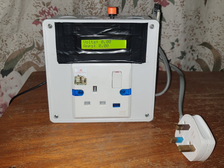
The smart energy monitor is a real-time domestic energy monitoring system. The features of this device are stated below.
- Periodic measurement of voltage, current, power, and energy that is drawn by a load from a socket or AC outlet in a building
- Periodic display of measured data on an LCD
- Periodic logging of measured data to an SD card
- Periodic data upload to the cloud (ThingSpeak Server and Google Sheets)
- Wi-Fi provisioning: To configure the SSID and password of the Wi-Fi network required by the system via a captive portal. The captive portal also configures voltage, current, power, and energy limits
- Sending notifications to the user (via an MQTT mobile application) whenever the measured parameters exceed their limits.
- ESP32 development board (e.g. DevKit V1, DevKitC-V4, or a custom board that can be manufactured by Seeed Studio)
- PZEM-004T-100A power module
- 16x2 LCD (with PCF8574T I/O expander)
- DS3231 RTC module
- SD card module
- 2GB SD card
- AC power socket
- 3-pin AC power plug
- Jumper wires
- LM7805 regulator
- LM2596 buck converter module
- Logic level shifter
- SPDT switch
SOFTWARE ARCHITECTURE AND TOOLS
The system was developed using the ESP-IDF FreeRTOS software platform. The ESP32 was programmed using C++. The code enables real-time measurement and display of current, voltage, power, and energy consumption, as well as data logging to an SD card and data upload to the ThingSpeak server and Google Sheets. The architecture for the embedded software developed for the smart energy monitor is summarized with a block diagram shown below.
The software tools used in this project include:
- Arduino IDE
- ESP-IDF FreeRTOS: To execute different tasks concurrently
- ThingSpeak: To visualize data
- IFTTT: To upload data to Google Sheets
- MQTT Dashboard: A mobile app to notify the user when energy limits have been exceeded. The smart energy monitor sends notifications to an MQTT broker (HiveMQ was used). The MQTT dashboard receives these notifications from the broker and alerts the user.
HAND TOOLS
- Soldering iron
- Mini drill
- Hot glue gun
- Plier
- Screwdriver
- Multimeter
SOME IMAGES OF THE PROTOTYPE
STEPS INVOLVED IN DEVELOPING THE PROTOTYPE
- Individual testing of components
- Implementation of the circuit on a breadboard
- Development and testing of the embedded software to interface the ESP32 with the other components
- Soldering of components on a veroboard to create permanent connections
- Testing of the complete circuit that was implemented on the veroboard
- Enclosing the complete circuit in a plastic box
Additional information can be found in the Github repository for this project. The repo contains the schematic, images, video demos, source codes, and more. The source codes can be found in a folder titled Energy_monitor in the repo. Link to the repo: Smart_Energy_Monitor_Repo
ACKNOWLEDGMENT- Publishing sensor data to Google Sheets
- ESP32 IFTTT sample code
- PZEM-004T sample code and current transformer connection diagram
- All libraries used e.g. WiFi manager library by Tzapu
- Seeed Studio (Seeed Studio Fusion PCB Assembly Service takes care of the entire fabrication process from Seeed Studio Fusion Agile manufacturing and hardware customization, parts sourcing, assembly, and testing services, so you can be sure that you are getting a quality product. Check more details here: Main page)


_4YUDWziWQ8.png?auto=compress%2Cformat&w=48&h=48&fit=fill&bg=ffffff)


_Ujn5WoVOOu.png?auto=compress%2Cformat&w=40&h=40&fit=fillmax&bg=fff&dpr=2)


_3u05Tpwasz.png?auto=compress%2Cformat&w=40&h=40&fit=fillmax&bg=fff&dpr=2)
Comments