Save some cash, and create a DIY drone using an Arduino Uno. Any high-performance drone on the public market will cost upwards of hundreds of dollars. But don't fear. A custom drone can cost as little as ten dollars, with a custom PCB and microchip.
In this project, I will walk through the steps to building one's own drone using balsa wood and an Uno.
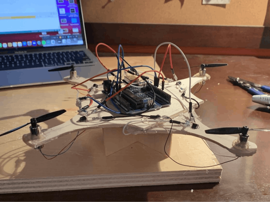
Step One: The SkeletonYou may be asking: why are drones typically made with four propellors in a diamond shape? The design above, version one of the drone project, is based upon a number of physics principles, most notably torque. Torque is a drone's worst enemy. Torque is the ability of a force to cause rotation, and thus, drone designers need to minimize it or eradicate it in order to have a functional project (a spinning drone wouldn't have too much use). Since torque is a function of displacement and force, each arm extension is equal length and equidistant from one another. The arm extensions are as thin as possible to optimize air flow and thrust. Finally, the base has a stand, so the motors don't brush against the ground, which could damage the connections.
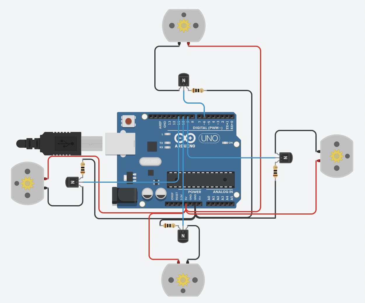
Step Two: The CircuitAt first glance, the circuit may seem complex; however, it consists of the same general topology modeled four times, for each motor. A ten ohm resistor, used to reduce heat and voltage across the transistor which has an 800mA max operating current, is in series with the NPN transistor on the GND-emitter side. The base of the BJT is connected to an analog voltage pin. The collector is connected to the GND side of the motor. Finally, the Vcc side of the motor is connected to 5V. Repeat this circuit for all four motors, soldering the GND and Vcc leads of each motor together.
Note: operating voltages and currents will vary based on the components you buy when designing your version of this project. I encourage you to look at the data sheets of your components.
Step Three: The CodeCompared with the circuitry, the code for the drone project is simple, considering the purpose for my version of the drone. For my drone, I only programmed it to fly straight up and hover and not to fly directionally.
Step Four: Going FurtherThe image you see above is version two of the drone. Not only can the skeleton of the drone be optimized and upgraded but so can the code and hardware. Beside designing a custom PCB and using a smaller microchip, a lighter skeleton and a light external power source are good places to start to make the drone more maneuverable. In addition, if you would like to make your drone move in more pre-coded patterns than just hovering, increase the analog voltages at two transistor bases on one side to make the drone move in the opposite direction. For example, to make the drone fly left, increase the voltages of the two transistors on the right. Via the principle of superposition, if you want to make it fly in two directions at once, make two sides of transistors have higher voltages. For example, to make it fly left and forward, apply higher base voltages to the transistors on the back and right sides of the drone.
A remote control can even be added to the project to make it move in unique patterns in real time. I would recommend using radio wave communicators, such as the nRF24L01, or various infrared transceivers.
Note: make sure you have enough thrust from your propellors and motors in order for the drone to fly. See data sheets of specific components. Typical units of thrust should be in pounds or newtons. Make sure the combined thrust of the four motors is greater than the weight of the drone itself.
Step Five: DiscoverCheck out my other projects on my dashboard:
- Arduino Smart Traffic Light
- Blindsight: a Wearable Device that Aids the Visually Impaired
- IAADL: an Infrared Activated Automatic Door Lock
- Arduino Functions Library
Check out all of my projects code at my GitHub repository.


_ztBMuBhMHo.jpg?auto=compress%2Cformat&w=48&h=48&fit=fill&bg=ffffff)


Comments
Please log in or sign up to comment.