SG Electronic Systems was born as a support to the Open Hardware projects. Our experience allows us to support the Open Hardware team in the development of new electronic systems and in their distribution. We have a long experience in Fieldbus applications as: CAN BUS, RS-232, RS-422/485, Ethernet.
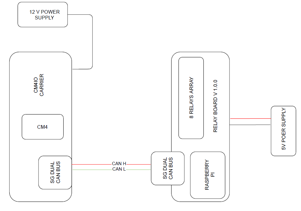
In this tutorial we explain how to control the Relay Board with can bus. The hardware setup is composed by Master Board (to send CAN commands) and Slave Board (for Relays control). The Master Board is the official carrier CM4IO with a CM4 module and CAN BUS Shield. The Slave Board is the Relay Board whit a Raspberry Pi 4 and DUAL CAN BUS Shield.
The CM4IO requires a 12 V DC power supply, instead the Relay board require a 5 V DC power supply (max allowed value is 5.1 V). On can side, the connection requires a a couple of wires for CAN High and CAN Low (CAN High is connected with CAN High, CAN Low is connected with CAN Low).
On both Raspberry Pi edit /boot/config.txt modify the following row
dtoverlay=mcp2515-can0, oscillator=16000000, interrupt=22dtoverlay=mcp2515-can1, oscillator=16000000, interrupt=25
Run the following command:
pi@raspberrypi ~ $ dmesg | grep -i can
This is the output:
[ 13.197388] CAN device driver interface[ 15.375846] mcp251x spi0.0 can1: bit-timing not yet defined[ 15.382408] mcp251x spi0.1 can0: bit-timing not yet defined
From the output it is possible to observe that can0 is associated to spi0.1 and can1 to spi0.0.
Respect the board shown in figure 1 the interface can0 is located in SPI0.1(X2 connector) and can1 in SPI0.0(X1 connector).
After your raspberry has been booted, go to home directory:
cd /home/pi/nano can-start.sh
add these lines to the script
#!/bin/sh#Canip link set can0 up type can bitrate 1000000ip link set can1 up type can bitrate 1000000
Run the script:
sudo sh can-start.sh
Before to start test with Python, you must test if the can bus communication works. You can use standard can bus commands to use the peripheral:
on first board run candump can0 -> to monitoring can bus traffic
on second board cansend can0 7DF#0201050000000000 -> to send canbus commands
If CAN BUS communication works fine, you can proceed with next step.
On our demo we use Python, all our scripts are ready for download. For scripts execution it is mandatory to install Python, and several libraries for GPIO, can and arguments parser on both boards. Run the following commands:
sudo apt-get update
sudo apt-get install python3-pip
sudo pip3 install RPi.GPIO
sudo pip3 install argparse
sudo pip3 install can
On Slave Board we can run the script
python relay_mcp2515.pyThe slave script switch off all relays and start CAN message listen with Id 0x1B2
Start can bus on Master Board and run the script
to send CAN commads. The script execution requires two argument Relay number (from 1 to 8) and Relay status (on/off), for example to switch on relay 1 use
python set_can_relay.py --rel 8 --status oninstead to switch off relay 8 use
python set_can_relay.py --rel 1 --status off


Comments
Please log in or sign up to comment.